Introduction

Goal

For this milestone, we needed to have a system that displays both the walls and the treasures in a maze as the robot finds them. Additionally, we needed our system to display a "done" signal on the screen and play a "done" tune on the speaker when the maze had been mapped completely.

Robot

MUX

In the previous milestone, we discussed how our mux was working improperly and not outputting the correct values. Turns out, we forgot to initialize the pinmode of the digital pins used for the select signal and that was causing incorrect readings. With this simple fix, our muxes work properly.

Another issue we came across while working on this milestone was an inadequate number of digital pins. In our previous design, we had decided to use two muxes, one for the wall sensors and one for the treasure sensors. This meant we needed digital pins for each select signal. Our radio already takes up digital pins 9-12 and that cannot be changed as those pins are required for SPI communication. We also needed pins for the LEDs to show which frequency of treasure we have found. Each servo takes up a digital PWM pin as well. Due to our limited amount of digital pins (only 5 left after the radio and servos are plugged in), we decided to simply use one mux for both the treasure and wall sensors. We needed 3 digital select bits for the 8 to 1 mux and the remaining 2 digital pins are used for the LEDs. The select signal and which signal they correspond with is as follows:

Select Bits Input Number Sensor Output
000 Y0 Left Wall Sensor
001 Y1 Front Wall Sensor
010 Y2 Right Wall Sensor
011 Y3 Empty
100 Y4 Left Treasure Sensor
101 Y5 Front Treasure Sensor
110 Y6 Right Treasure Sensor
111 Y7 Empty
In the future, we will also add our microphone to one of the empty input slots.

Treasure Sensors

We positioned 3 treasure sensors on the left, front and right sides of our robot. Our treasure sensor code from lab 2 only needed minor changes when incorporating it into our main algorithm. We created two different functions for our main code. The first is called detect_treasure() and returns a character. This character signifies if there is no treasure (returns 0), the treasure is 7kHz (returns 1), the treasure is 12 kHz (returns 2) or the treasure is 17 kHz (returns 3). This function also iterates through each of the select bits as follows in order to check all 3 sensors.


                            			digitalWrite(s2, HIGH);
							  for (int i = 0; i < 3; i++) {
							    digitalWrite(s0, LOW);
							    digitalWrite(s1, LOW);
							    if (i & 1) {
							      digitalWrite(s0, HIGH);
							    }
							    if (i & 2) {
							      digitalWrite(s1, HIGH);
							    }
                            

The biggest change we needed to make to our treasure sensor code was the number of bins we were using. We originally defined FFT_N as 256, but quickly realized this takes up a lot of memory on the arduino and would potentially cause issues. In order to fix this, we reduced the amount of bins from 256 to 128. Because the bins were now of different widths and contained different frequencies, we analyzed the bin outputs when a treasure of each frequency was present. We knew the bin numbers that we should be checking would be around half the bin number of the original bins we checked. Below is an example of a graph of the sensor output vs. the bin number when a 12 kHz treasure is present.

Based on this graph, we chose to check if bins 40, 41 and 42 were all above 60. We repeated this process for the 7kHz and 17kHz treasures and produced the following code for detect_treasure()

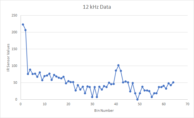
                        				int seven = fft_log_out[24] + fft_log_out[25];
						    int twelve = fft_log_out[40] + fft_log_out[41] + fft_log_out[42];
						    int seventeen = fft_log_out[57] + fft_log_out[58] + fft_log_out[59];
						    
						    if (seven > 120){
						      treasure = 1;
						    }

						    else if (twelve > 180){
						      treasure = 2;
						    }

						    else if (seventeen > 180){
						      treasure = 3;
						    }
						    if (treasure != 0) {
						      ADCSRA = 0xc0; //turn off free running mode
						      return treasure;
						    }
						  }
						  ADCSRA = 0xc0; // Turn off free running mode
						  return treasure;


You will also notice that at the end of our code, we needed to reset the ADCSRA so that we were not in free running mode and could use analogRead for the rest of our main code. The next function we wrote was checkTreasure(). This function turns on the appropriate LED and updates the current maze square to reflect that there is a specific treasure present in that square of the maze. Each position in the maze is represented as a single byte and bits 6 and 7 represent treasures. If those bits are 00, there is no treasure, if 01, there is a 7kHz treasure, if 10, there is a 12 kHz treasure and if 11, there is a 17 kHz treasure. Below is the function checkTreasure().

                        	
                        		   		#define SEVEN  64
							#define TWELVE  128
							#define SEVENTEEN 192
                        	void checkTreasure(){
							  char treasure = detect_treasure();
							  if (treasure ==1){
							    digitalWrite(GREEN, HIGH);
							    digitalWrite(BLUE, HIGH);
							    maze[currentRow][currentColumn] |= SEVEN;
							  }
							  if(treasure==2){
							    digitalWrite(GREEN, HIGH);
							    maze[currentRow][currentColumn] |= TWELVE;
							  }
							  if (treasure ==3){
							    digitalWrite(BLUE, HIGH);
							    maze[currentRow][currentColumn] |= SEVENTEEN;
							  }
							  
							}
							

Since we only had enough digital pins for 2 LEDs, we decided to, instead of turning on a red LED for 7kHz, turn on both the blue and green LEDs. This function is called at every junction we reach.

Radio

Our Radio code was very similar to the radio code from lab 4, we just needed to change the data we were sending. We chose to send two bytes of information after every time we reach a junction and check for walls and treasures. The first byte characterizes the current square the robot is in and is as follows:

bit 7 bit 6 bit 5 bit 4 bit 3 bit 2 bit 1 bit 0
Treasure bit 1 Treasure bit 0 visited unreachable West wall present South wall present East wall present North wall present
We define the north wall as the wall in the direction the robot starts the maze. We assume the robot starts the maze in the bottom right corner. The second byte is used the represent which row and column the robot is in and is as follows:
bit 7 bit 6 bit 5 bit 4 bit 3 bit 2 bit 1 bit 0
unused unused unused Row bit 2 Row bit 1 Row bit 0 Column bit 1 Column bit 0
In our main algorithm, each square in the maze is already an 8 bit character that follows the structure of the first byte. We have a function that takes in that byte, the current row and the current column and then sends this information to the arduino at the base station. We store the two bytes in the variable data_buffer. That function is as follows:

		                    bool transmit_node(char node, int row, int column){
							  char data_buffer[2];
							  row = row<<3;
							  char coords = row | column;
							  data_buffer[0] = node;
							  data_buffer[1] = coords;
							 
							  // First, stop listening so we can talk.
							  radio.stopListening();

							  // Take the time, and send it.  This will block until complete
							    
							  bool ok = radio.write( data_buffer, 2 );

							  if (!ok){
							    return false;
							  }

							  // Now, continue listening
							  radio.startListening();

							  // Wait here until we get a response, or timeout (250ms)
							  unsigned long started_waiting_at = millis();
							  bool timeout = false;
							  while ( ! radio.available() && ! timeout )
							    if (millis() - started_waiting_at > 200 )
							      timeout = true;

							  // Describe the results
							  if ( timeout )
							  {
							    return false;
							  }
							  else
							  {
							    // Grab the response, compare, and send to debugging spew
							    char got_data[2];
							    radio.read( &got_data, 2 );
							    if(got_data[0]!=data_buffer[0] | got_data[1]!=data_buffer[1]){
							      return false;
							    }

							  }

							}
		                    

In the main code, if the function returns false when called, we send the data again.

Algorithm

The main loop of our alrgorithm calls functions to check for walls, check for treasures and then move to a new node in the maze. At each junction, we send information about that square to the base station. Once the entire maze has been traversed and mapped, the blue and green LEDs alternate flashing on and off. The main loop of our algorithm is as follows:


                              				maze[4][3] |= VISITED;
								  check();
								  checkTreasure();
								  transmit_node(maze[currentRow][currentColumn], currentRow, currentColumn);
								  possibleMove();
								  while(backTrackPointer != 0){
								    check();
								    checkTreasure();
								    transmit_node(maze[currentRow][currentColumn], currentRow, currentColumn);
								    possibleMove();
								    digitalWrite(GREEN, LOW);
								    digitalWrite(BLUE, LOW);
								  }
								  while(1){
								    digitalWrite(GREEN, HIGH);    
								    delay(1000);
								    digitalWrite(GREEN, LOW);
								    digitalWrite(BLUE, HIGH);
								    delay(1000);
								    digitalWrite(BLUE, LOW);
								  }
                            

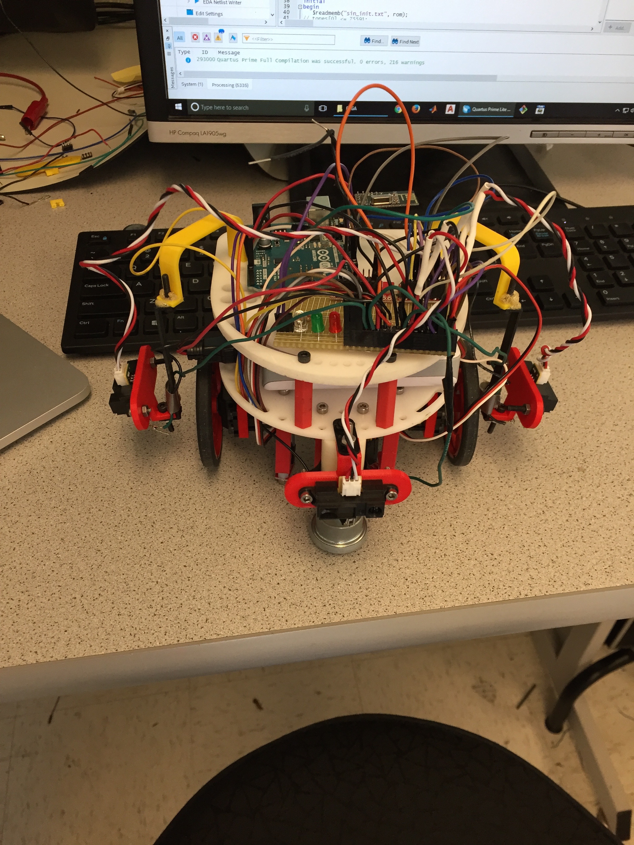
Here's a picture of our current robot and a video of our robot's current maze traversal capabilities.

<
Base Station

Setup

In order to recieve the two bytes of maze information sent from the robot, we need an arduino with a wireless radio connected to digital pins 9-13. We also decided to use the SPI serial communication protocol to communicate between the base station's arduino and the FPGA. To do this, we needed four connection lines between the arduino and the FPGA: clock (SCK), MOSI (master-out, slave-in), MISO (master-in, slave-out), and slave-select (SS). The SCK, MISO, and MOSI lines are connected to arduino pins 13, 12, and 11, respectively. We also assigned the SS pin for SPI communication to be digital pin 4. In order to read in data from the wireless radio, pin 10 needs to be set low and pin 4 needs to be set high. In order to transmit date to the FPGA, pin 10 needs to be high and 4 needs to be low. All the pins connected to the FPGA must also go through a voltage divider first to step the voltage down from 5V (which is the output voltage of the arduino digital pins) to 3.3V (which is the input voltage of the GPIO pins on the FPGA) by using 330 Ohm and 680 Ohm resistors. The picture below shows the radio connected to the arduino (via the light blue wires), the arduino digital pins outputting to the voltage divider on the breadboard, and the outputs from the voltage divider connecting to four GPIO pins on the FPGA (via the orange, black, blue, and green wires).

Radio

The receiving radio code is also similar to that of lab 4. The following code shows how we read in the two data bytes and then use SPI to transfer them to the FPGA. We had to include the SPI Library for Arduino in order to make use of the function SPI.transfer() which indicates the Arduino will send the given information to the FPGA using the SPI protocol. We manipulate the low-enabled SS by using digitalWrite() to set SS to low to indicate the Arduino will be sending information.


							if ( radio.available() )
							  {
							    unsigned char got_data[2];
							    bool done = false;
							    while (!done)
							    {
							      // Fetch the payload, and see if this was the last one.
							      done = radio.read(&got_data, 2 );

							      delay(20);

							    }

							    // First, stop listening so we can talk
							    radio.stopListening();

							    // Send the final one back.
							    radio.write(&got_data, 2 );

							    //switch to FPGA and send data

							    digitalWrite(SS, LOW);
							    SPI.transfer(got_data[2]);
							    digitalWrite(SS, HIGH);

							    // Now, resume listening so we catch the next packets.
							    radio.startListening();
							  }
							

FPGA

Using the FPGA, we needed to display all of the maze information on the VGA display, including the walls, any treasures, and the robot's current and previous locations. In order to display a 5x4 grid on the VGA monitor, we chose to subdivide the display into 10 pixel x 10 pixel squares. Using this convention, we made the wall widths 10 pixels and all the actual grid spaces 80 pixels x 80 pixels. With five wall spaces and four grid spaces in the x-direction and six wall spaces and five grid spaces in the y-direction, our entire maze takes up a 370 pixel x 460 pixel area on the monitor. We chose the following coloring convention for the maze:

  • Red = Unvisited grid space
  • Green = Robot's current position
  • Blue = Already visited grid space
  • Black = Wall
  • White = No Wall
  • Pink = 7 kHz treasure at that grid space
  • Yellow = 12 kHz treasure at that grid space
  • Orange = 17 kHz treasure at that grid space
This picture shows our initialized maze before it has been traversed, with no interior walls and all unvisited grid spaces.

Following the maze initialization on the VGA monitor, we needed to develop a scheme to update the maze according to the incoming data from the robot. As discussed above, all the information needed to properly update the maze is encoded in the two bytes sent from the robot to the base station via the wireless radios. We needed to parse these two bytes and make the necessary changes to the maze on the display.

Bits 4 through 2 in the second byte encode the row of the robot's current position, which can be from 0 to 4 (000 to 100 in binary). Bits 1 and 0 in the second byte encode the column of the robot's current position, which can be from 0 to 3 (00 to 11 in binary). We can then map this position to the corresponding pixels on the display and set those pixels to green (for robot's current position). When the next data transmission is received by the base station, and the robot moves to another position, we can set these pixels to blue (for already visited).

If bits 7 and 6 in the first byte ever indicate that a treasure has been found at a position, then we can set the pixels corresponding to that position on the display to the correct treasure color (pink, yellow, or orange). Bits 3 to 0 in the first byte indicate the walls surrounding the robot's current position. If, for example, bit 3 is a 1 (meaning there is a wall to the west), then we can set the 80x10 pixel area to the left of the current grid space to black (indicating a wall). The same idea applies for walls to the east, south, and north.

When we are done traversing the maze, any unvisited positions on the grid can remain colored red, indicating that they are unreachable. Additionally, we will signal "done" on the VGA display somehow (flashing pixels on the display, coloring the display a certain way, etc.).

We will also play a "done" tune on the lab speakers when the robot has finished traversing the maze. By modifying the code we had from Lab 3 for generating sine waves of multiple frequencies, we were able to work out the frequencies and durations of the notes in "Jingle Bells." We then coded this tune into our AUDIO.v file and made an instantiation of AUDIO in our DE0_NANO.v file.


                                AUDIO audio(
                                    .RESET(reset),
                                    .CLK(CLOCK_25),
                                    .SW(SW),
                                    .SOUND({GPIO_1_D[22],GPIO_1_D[20],GPIO_1_D[18],GPIO_1_D[16],GPIO_1_D[14],GPIO_1_D[12],GPIO_1_D[10],GPIO_1_D[8]})
                                );
                            

A "done" signal from the robot can act as the enable signal for both the "Jingle Bells" tune on the speakers and the "done" signal on the VGA monitor.

Below is our current base station circuitry, with the lab speakers connected to GPIO pins on the FPGA via the 8-bit R2R DAC.