Team Members
- Nicolas Casazzone
- Alicia Coto
- Raul Pacheco
Materials
- 2x Arduino Uno
- 2x Nordic nRF24L01 + Tranceivers
- 2x USB A/B Cables
- 2 Radio Breakout Boards with Headers
Establishing Wireless Communication
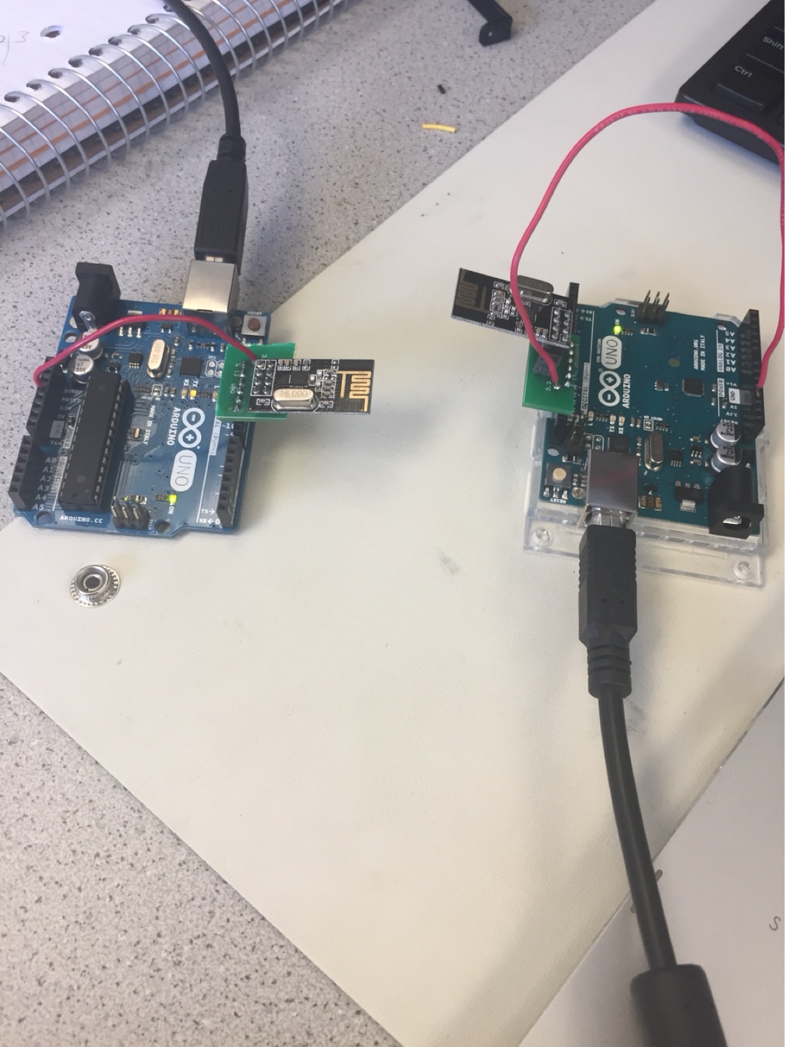
The Nordic nRF24L01 + tranceivers have been already printed as a single circuit board. We plugged this radio into the 13-9 digital pins of the Arduino and connected the red cable to the 3.3V Arduino power supply pin.
After properly connecting the radios to the Arduino boards, we downloaded the RF24 Arduino Library and added it to our Arduino directory. To code our radio communication scheme, we modified the "Getting Started" sketch included in the R24 Library. In order to designate the receiving and transmitting channels for our Arduinos, we used the formula :
2(3D + N) + X
Where D is our lab data (Monday = 0), N is our team number (Team 2 = 2), and X is either 0 or 1 to identify the two radios.
The solved values for our two radios were 4 and 5. Within our "Getting Started" sketch, we had to modify the radio addresses to 4 and 5 in decimal.
                        // Radio pipe addresses for the 2 nodes to communicate with addresses 4 and 5
                        const uint64_t pipes[2] = { 0x0000000004LL, 0x0000000005LL };
Once both Arduinos were programmed with the GettingStarted code, in order to observe the data being transmitted and recieved, we had to open the serial monitors (set to a baud rate of 57600). To chose which radio will transmit, we needed to type a "T" into one serial monitor, and then an "R" into the serial monitor corresponding with the radio we wanted to recieve data.
Another thing to note is that the RF24 library contains a feature called Auto-ACK which ensures that the correct amount of bytes are recived in a single payload. For example if a byte is not recieved, the transmitter will be aware of that instead of thinking the first byte in the next payload belongs to the previous payload. The feature automatically sends an acknowledgment packet once the transmitter has recieved and validated a packet sent from the reciever. If this were to be turned off, our data could be wrong if a byte is lost in communication.
Communicating the Entire Maze
In order to transmit the whole maze, we needed to have a system to define each type of square we could have in the maze. For this lab, we used 2 bits to identify a square in the maze. Zero signifies an unvisited square, one signifies a visited square, two signifies a treasure, and three signifies a wall. We created an area of unsigned characters to send in a single payload, representing a 4 by 5 maze. The default size of a payload is 32 bytes, so this array fits in a single payload. Below is an example of such an array.
                        unsigned char maze[4][5] =
					      { 0, 1, 1, 0,
					        0, 0, 2, 0,
					        0, 3, 1, 3,
					        0, 3, 1, 3,
					        0, 0, 0, 0,
					      };
We then used the command radio.write(&maze, sizeof(unsigned long)) to send the maze information. When the second radio recieved the maze, which was done using the radio.read command, the maze would be printed to the serial monitor and then sent back to the transmitting radio in order for the transmitter to know the payload sent successfully.
Updating New Maze Data
Always sending the entire maze can be taxing. In order to improve efficiency, we can simply update one sqare of the maze at a time when our robot discovers something new. We divised a way to send this information in one byte. The first two bits correspond to the x coordinate (columns 0, 1, 2, or 3). The next 3 bits correspond to the y coordinate (rows 0, 1, 2, 3, or 4). The last 3 bits can be used to define the type of sqare is at these coordinates. Previously we only used 2 bits to determine this information, but we decided in the future we may want to add more states. Below is an example of a square being updated.
                        unsigned char x_coord = 2;
                        unsigned char y_coord = 4;
                        unsigned char pos_data = 3;

                        unsigned char new_data = x_coord << 6 | y_coord << 3 | pos_data;
The byte is constructed by shifting each portion of data into the correct bit position using the bitwise shifting operator ("<<"). Then we concatenated the three pieces of data by useing the bitwise or operator ("|"). In this example, the byte to be sent is 10100011. Once this data is read by the reciever, the reciever prints out the decimal value (163 in this case) and sends back the byte.