Milestone 2
ECE 3400 Team 2 Fall 2017
Goal
The purpose of this milestone was to add at least one IR treasure sensor and one wall detection sensor to our robot. We needed to be able to use the IR treasure sensor to detect and distinguish between the 7 kHz, 12 kHz, and 17 kHz treasures. Using the wall sensor, we needed our robot to be able to autonomously detect walls and avoid collisions with them.
Materials Used
- 1 Arduino Uno
- 1 USB A/B Cable
- 1 IR Treasure Sensor
- Treasure Board (Borrowed from TA)
- 1 Wall Detection Sensor
- 3 Different Color LEDs
- Various Resistors
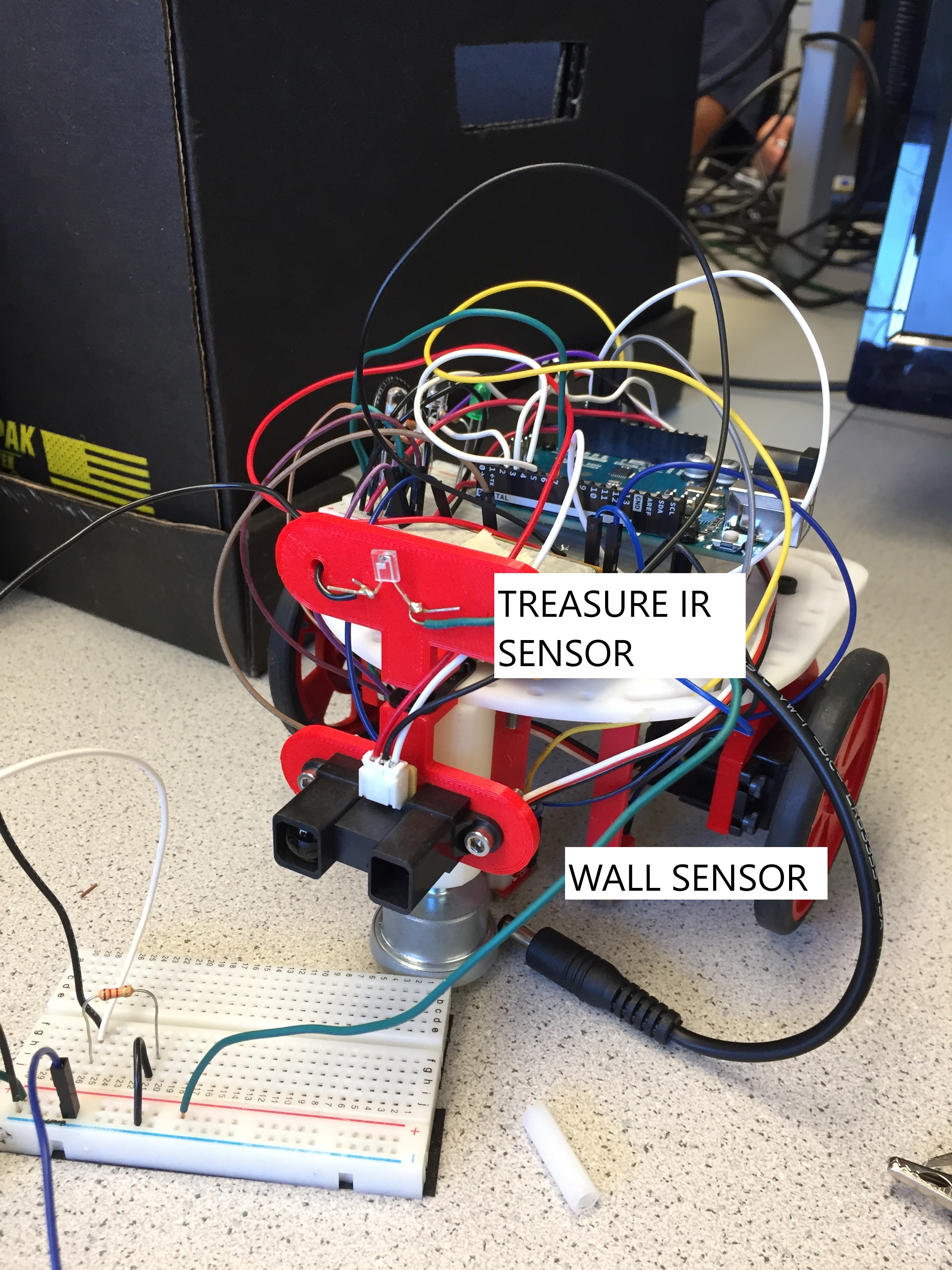
For this milestone, we only needed to implement the basic functionality of wall detection. We mounted one wall detection sensor onto the front of our robot in order to detect walls directly in the robot's path.
In order to allow the robot to navigate with this new sensor on, we kept the same turning, line-following, junction detection, and step-past-junction functions that we used for Milestone 1. However, we needed to add a new function for wall detection. To meet this need, we added this function:
                            bool detectWall() {
                                int wall = analogRead(wallpin);
                                if (wall>400) {
                                    return true;
                                }
                                else {
                                    return false;
                                }
                            }
We connected the output from the wall sensor to analog pin A3, which we assigned the name "wallpin". We then viewed the input data using the serial monitor to observe how the values changed as we varied the distance from the sensor to a wood block. We decided that as soon as the input value surpassed 400, the boolean detectWall() should be set to true, indicating our robot is approaching a wall.
For this milestone, our algorithm for handling a detected wall was very simple. If our robot detected a wall in front of it, we wanted it to turn left at the next junction. We also added in a second left turn in the case that after the first, there was still a wall in our path. In this case, the robot would simply turn back and move in the direction it came from. We wrote the following code to accomplish this:
                            void loop() {
                                // put your main code here, to run repeatedly:
                                moveForward();
                                while (detectJunction()==false){
                                    moveForward();
                                }
                                if (detectWall() == true){
                                    stepPastJunction();
                                    turnLeft();
                                    if (detectWall() == true){
                                        stepPastJunction();
                                        turnLeft();
                                    }
                                }
                                else {
                                  moveForward();
                                }
                            }
Finally, we set up a small course for our robot to navigate in order to verify that our wall detection code was running the way we intended.
Wall Detection
We first mounted the IR sensor onto the front of our robot.
We then reconstructed the basic treasure detection circuit from Lab 2, placing the resistor in the schematic on the breadboard of our robot.
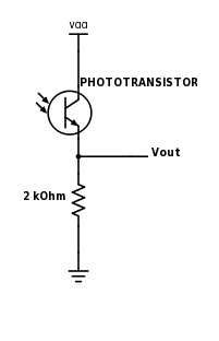
We connected the output from our treasure detection circuit to analog pin A0 on the arduino and used the fft functionality of the arduino to view the output on the serial monitor. In particular, we wanted to see which bins in the fft data had peak amplitude for each signal frequency. Using the adjustable treasure board, we were able to create the 7 kHz, 12 kHz, and 17 kHz IR treasure signals. At each frequency, we held the treasure board up in front of the treasure sensor on the robot and observed the fft data on the serial monitor. So that we detected the proper frequncies, we needed to adjust the 'prescaler' which adjusts the sampling rate for the IR sensor. We set the prescaler to 32, which results in a 38.4 kHz sampling frequency and 128 bins with widths of 150 Hz. We chose this prescaler because we needed to detect a signal up to 17 kHz and with a prescaler of 32 the max frequency we can detect is 19.2 KHz. (In lab 2, we set the prescaler to 64 because we only needed to detect 7kHz.) For the 7 kHz IR signal, the peak amplitude was in bin 47. For the 12 kHz IR signal, the peak amplitude was in bin 80. For the 17 kHz IR signal, the peak amplitude was in bin 113.
After observing the fft data values for each treasure frequency, we noticed that monitoring just the peak amplitude bin for each frequency was not the most accurate way to detect the treasures. Instead, we found that monitoring the peak amplitude bin along with the bins immediately before and after it, and then taking a summation of the three, allowed us to more accurately distinguish when the sensor was actually detecting a treasure. We found that if the sum of these three bins exceeded a magnitude of 300, then we could be confident that a treasure was being detected.
To test our robot's treasure detection, we then wrote the following segment of code:
                            int seven = fft_log_out[46] + fft_log_out[47] + fft_log_out[48];
                            int twelve = fft_log_out[79] + fft_log_out[80] + fft_log_out[81];
                            int seventeen = fft_log_out[112] + fft_log_out[113] + fft_log_out[114];

                            if (seven > 300){
                                digitalWrite(2,HIGH); //7kHz detected
                                delay(2000);
                                digitalWrite(2,LOW);
                            }

                            if (twelve > 300){
                                digitalWrite(4,HIGH); //12kHz detected
                                delay(2000);
                                digitalWrite(4,LOW);
                            }

                            if (seventeen > 300){
                                digitalWrite(7,HIGH); //17kHz detected
                                delay(2000);
                                digitalWrite(7,LOW);
                            }
The bin magnitude summations for the 7 kHz, 12 kHz, and 17 kHz signals were assigned to the variables "seven", "twelve", and "seventeen", respectively. We connected a green LED to digital pin 2, a blue LED to digial pin 4, and a red LED to digital pin 7. In our setup code, we initialized these three pins to act as outputs.
                            //Treasure Sensors
                            pinMode(2, OUTPUT); //7kHz
                            pinMode(4, OUTPUT); //12kHz
                            pinMode(7, OUTPUT); //17kHz
If "seven", "twelve", or "seventeen" ever exceeded a magnitude of 300, then we assigned its corresponding digital output to HIGH for two-second flashes: "seven" corresponded to pin 2, "twelve" to pin 4, and "seventeen" to pin 7. With this set up, the 7 kHz treasure caused the green LED to flash, the 12 kHz treasure caused the blue LED to flash, and the 17 kHz treasure flashed the red LED, as can be seen below.