Introduction

Goal

The next step in developing our robot is to allow it to sense the world around it. Our robot can currently move throughout its environment, but has no knowledge about where it is or what is around it. For this lab, we developed two different sensors to be used on our robot. First, we used a microphone circuit to detect a 660Hz whistle blow. This tone is used to signal our robot to begin exploring the maze. The second sensor was an IR sensor to detect various treasures which blink at varying frequencies.

Open Music Labs FFT

In order to analyze analog signals, it is often easy and useful to tranform them into the frequency domain from the time domain. This then allows us to examine the dominate frequencies contributing to a particular signal.

Luckily the arduino architecture has a large amount of open source third party code available for use. For this lab, we used Open Music Labs' FFT library to perform fourier transforms on our sensor data. Because this library is from a third party and is not included with the Arduino IDE download, we had to download the source code and place it in our libraries directory. Code and documentation of Open Music Labs FFT can be found here. Below is a command prompt showing the tree structure of the FFT library we downloaded.

Once we successfully downloaded the FFT library, we began using the example code provided to learn how to use the fourier transform to analyze analog signals. Below is the example code along with an explanation of what is being done.


                            /*
                            fft_adc_serial.pde
                            guest openmusiclabs.com 7.7.14
                            example sketch for testing the fft library.
                            it takes in data on ADC0 (Analog0) and processes them
                            with the fft. the data is sent out over the serial
                            port at 115.2kb.
                            */

                            #define LOG_OUT 1 // use the log output function
                            #define FFT_N 256 // set to 256 point fft

                            #include <FFT.h> // include the library

                            void setup() {
                                Serial.begin(115200); // use the serial port
                                TIMSK0 = 0; // turn off timer0 for lower jitter
                                ADCSRA = 0xe5; // set the adc to free running mode
                                ADMUX = 0x40; // use adc0
                                DIDR0 = 0x01; // turn off the digital input for adc0
                            }

                            void loop() {
                                while(1) { // reduces jitter
                                    cli();  // UDRE interrupt slows this way down on arduino1.0
                                    for (int i = 0 ; i < 512 ; i += 2) { // save 256 samples
                                        while(!(ADCSRA & 0x10)); // wait for adc to be ready
                                        ADCSRA = 0xf5; // restart adc
                                        byte m = ADCL; // fetch adc data
                                        byte j = ADCH;
                                        int k = (j << 8) | m; // form into an int
                                        k -= 0x0200; // form into a signed int
                                        k <<= 6; // form into a 16b signed int
                                        fft_input[i] = k; // put real data into even bins
                                        fft_input[i+1] = 0; // set odd bins to 0
                                    }
                                    fft_window(); // window the data for better frequency response
                                    fft_reorder(); // reorder the data before doing the fft
                                    fft_run(); // process the data in the fft
                                    fft_mag_log(); // take the output of the fft
                                    sei();
                                    Serial.println("start");
                                    for (byte i = 0 ; i < FFT_N/2 ; i++) { 
                                        Serial.println(fft_log_out[i]); // send out the data
                                    }
                                }
                            }
                        

The setup function for this code mainly deals with setting up the analog to digital converter. In the last lab, we used the provided function analogRead() to get an analog value from an analog input pin. However, the documentation for this function state that the execution time is approximately 100 microseconds (.0001 s). Therefore, the maximum sampling rate is approximately 10,000 Hz. Because we are trying to detect infrared signals up to 14 kHz, this is simply not fast enough. Therefore, we have to read the value directly from the analog to digital converter.

Within the loop function above, 256 samples are fetched from the ADC, and placed into even bins. When computing a fourier transform, there will be real and imaginary components. For the FFT library, even bins correspond to the real part, and odd bins correspond to the imaginary part. Since we are dealing with real signals, we will only write to and read from the even bins. Once all of the bins have been filled, You must process the data using fft_run(). For the purposes of this example, the bins are then outputted to the serial monitor. This code served as the basis for the development of both the acoustic and optic sensors.

Acoustic Subteam

Materials

  • Arduino Uno
  • Electret microphone
  • 300 Ohm Resistors
  • 1 μF Capacitor
  • ~3 kOhm Resistor
  • Various other components (breadboard, wiring, etc.)

Microphone Circuit

We began by assembling the basic circuit for the microphone shown on the lab handout. We used the 1 μF capacitor and a 2.7 kOhm resistor.

We then used a free internet application to generate a sustained 660 Hz tone for the microphone to pick up. We fed the output from the microphone into an oscilloscope to visualize the output. The output had a peak-to-peak amplitude of about 500 mV, and it did not have a great sinusoidal shape.

After playing around with our circuit, we realized that removing the resistor before the high voltage input to the microphone greatly increased the quality of our signal. While the resistor was initially in place to protect the microphone from too large a current, we realized that since the input voltage was only 5 V, the resistor was not completely necessary to protect the microphone itself. After making this change, the output from the microphone had a much better sinusoidal shape and a peak-to-peak amplitude of about 1 V.

In order to increase the amplitude of the signal to better distinguish it, we decided to add an amplifier. You can see the documentation for the amplifier circuit that we built below. We fed the output from our basic microphone circuit into our amplifier. We then took the output from our amplifier and connected it to analog pin A0 on our arduino.

The purpose of connecting the output from the amplifier to analog pin A0 was to allow us to view our signal data in the serial monitor and to enable us to use the arduino fft functionality. In order to test that we could distinguish between different frequency tones, we used the tone generator to create a 585 Hz tone, a 660 Hz tone, and a 735 Hz tone, one at a time. For each tone, we used the serial monitor to display the bin magnitude data. If each tone produced a peak magnitude in a different bin, then we would be able to distinguish between the tones relatively easily. As it turned out, they did. The 585 Hz tone produced a peak in bin 17. The 660 Hz tone produced a peak in bin 19. The 735 Hz tone produced a peak in bin 21.

These results demonstrate that we are indeed able to distiguish the 660 Hz start tone from similar frequency tones, which will be critical during the competition given the amount of background noise that will be in the Duffield atrium.

Optics Subteam

Materials

  • Arduino Uno
  • IR Reciever
  • 300 Ohm Resistor
  • Treasure Board (Borrowed from TA)
  • Miscellaneous Components (wires, screwdriver, etc)

PhotoTransistor Circuit

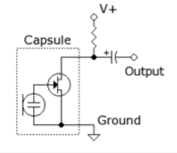
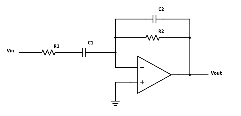
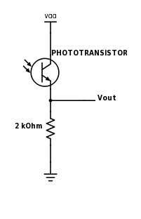
We began by wiring together a circuit to detect varying levels of infrared light. The sensor in this circuit is a photoresistor which will pass varying amounts of current through it depending on the amount of infrared light hitting it. We convert this variable current to a variable voltage by passing it through a resistor. Below is a simple schematic diagraming the basic circuit setup. Vout is them used as the analog input for the Arduino.

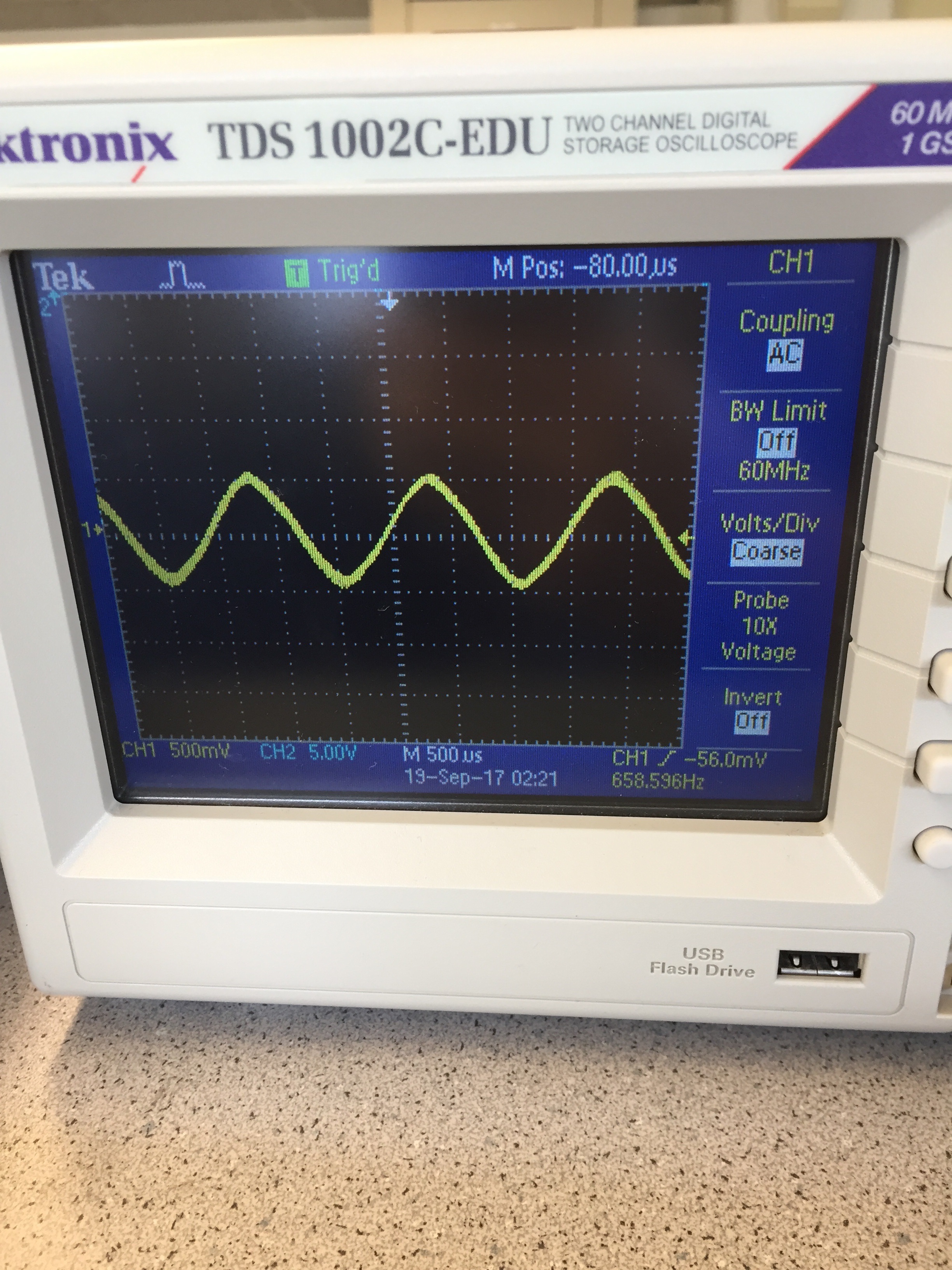
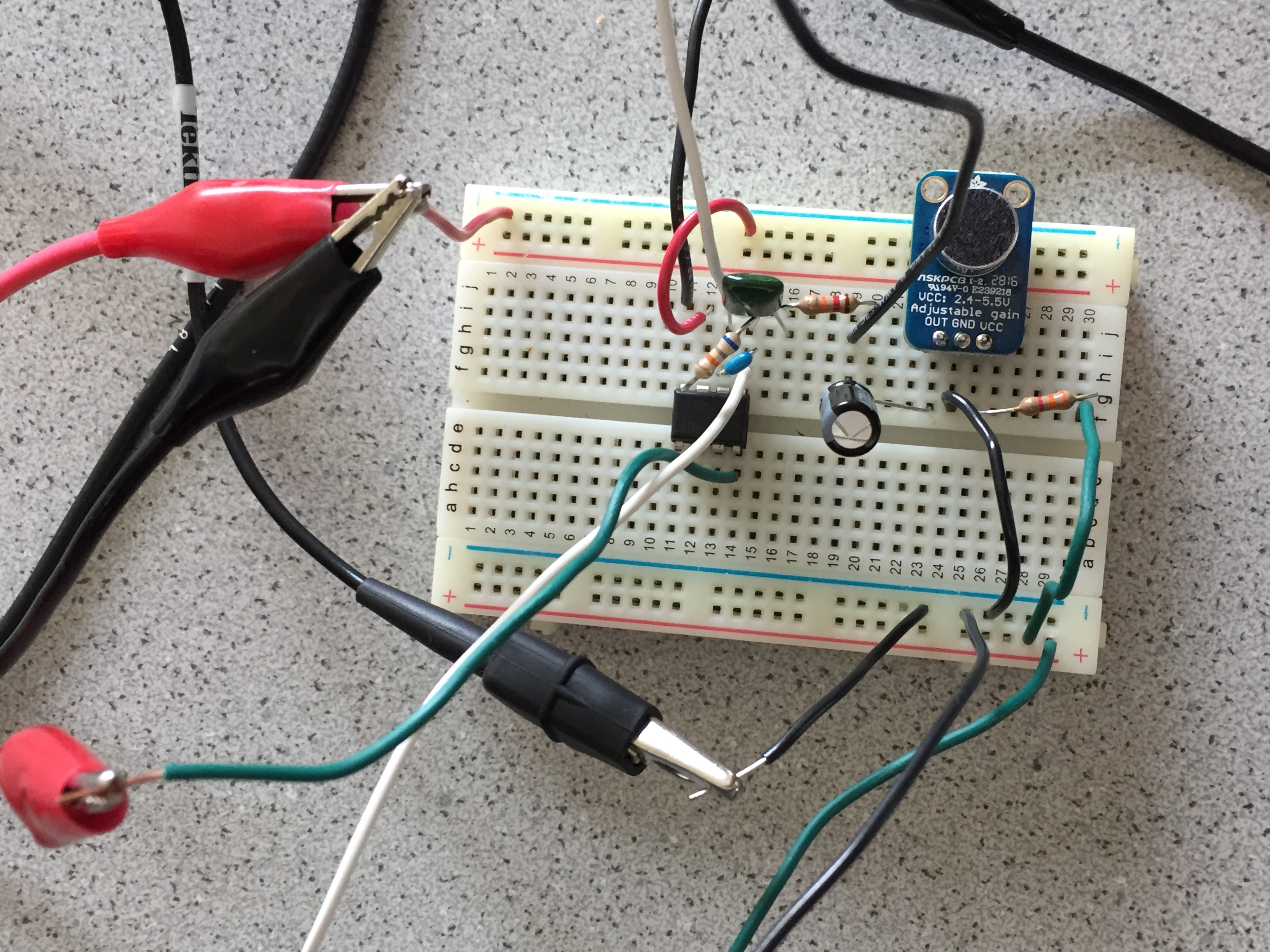
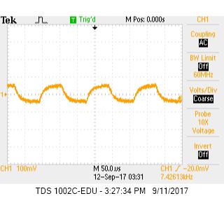
Once we had our circuit built, we began testing using the treasures. Borrowing a treasure from on of the TA's, we began by measuring the signal directly using the oscilloscope. By adjusting the pontentiometers on the treasure board, we were able to change the frequency and intensity of the infrared signal. Below is a screen capture of the oscilloscope. Note that the signal resembles the charge and discharge of a capacitor more than a standard sine wave. Because of this, the signal will contain a range of frequency components, however, the one we are interested in is the main tone. In this case, the treasure is tuned to about 7.4 kHz.

Now that we had our circuit built and tested the treasure board, we were ready to begin processing the signals using the Arduino. First, we passed the output of our sensor circuit through a 300 Ohm resistor, and into an analog input pin on the Arduino. We then wrote a program to read in the data, and perform a fourier transform to determine the dominant frequency components.

In order to analyze the data from the FFT, you need to know what each bin corresponds to. This depends on the sampling frequency. In order to spped up the sampling frequency, you must read the value directly from the ADC. The sampling frequency can then be changed by changing the clock prescalar for the ADC clock. By default, the ADC clock is 16 MHz with a default prescalar of 128. Therefore, the ADC clock is 16 MHz/128 = 125 KHz. Since a conversion takes 13 ADC clock cycles, the default sample rate is 125 KHz/13 = 9600 Hz. This sampling rate is not quite fast enough for our purpose, so we adjusted the prescalar to 64 to produce a sampling frequency of approximmately 19.2 KHz. In order to do this, we set the ADPS register to 110. Note, the below code adjusts the ADC clock prescalar as described, but we also generate a square wave with half this frequency on I/O pin 11. This was done to check the sampling frequency since at the time of the lab we were unable to find good documentation on the ADC clock and sampling frequencies.


                            /*
                            Infrared Sensor FFT
                            */

                            #define LOG_OUT 1 // use the log output function
                            #define FFT_N 256 // set to 256 point fft

                            #include <FFT.h> // include the library

                            bool high = true;

                            void setup() {
                                Serial.begin(9600); // use the serial port
                                TIMSK0 = 0; // turn off timer0 for lower jitter
                                ADCSRA = 0xe5; // set the adc to free running mode
                                ADCSRA &= ~(bit (ADPS0) | bit (ADPS1) | bit (ADPS2)); // clear prescaler bits
                                ADCSRA |= bit (ADPS1) | bit (ADPS2); // set prescalar to 64
                                ADMUX = 0x40; // use adc0
                                DIDR0 = 0x01; // turn off the digital input for adc0
                                pinMode(11, OUTPUT);
                            }

                            void loop() {
                                while(1) { // reduces jitter
                                    cli();  // UDRE interrupt slows this way down on arduino1.0
                                    for (int i = 0 ; i < 512 ; i += 2) { // save 256 samples
                                        // debugging purposes
                                        // outputs square wave with f = 1/2 sampling frequency
                                        if (high) {
                                            digitalWrite(11, LOW);
                                            high = false;
                                        }
                                        else {
                                            digitalWrite(11, HIGH);
                                            high = true;
                                        }
                                        while(!(ADCSRA & 0x10)); // wait for adc to be ready
                                        ADCSRA = 0xf5; // restart adc
                                        byte m = ADCL; // fetch adc data
                                        byte j = ADCH;
                                        int k = (j << 8) | m; // form into an int
                                        k -= 0x0200; // form into a signed int
                                        k <<= 6; // form into a 16b signed int
                                        fft_input[i] = k; // put real data into even bins
                                        fft_input[i+1] = 0; // set odd bins to 0
                                    }
                                    fft_window(); // window the data for better frequency response
                                    fft_reorder(); // reorder the data before doing the fft
                                    fft_run(); // process the data in the fft
                                    fft_mag_log(); // take the output of the fft
                                    sei();
                                    Serial.println("start");
                                    for (byte i = 0 ; i < FFT_N/2 ; i++) { 
                                        Serial.println(fft_log_out[i]); // send out the data
                                    }
                                }
                            }
                        

This code simply dumps the data from all of the even bins to the serial monitor. We then took this data, and graphed it to see the various frequency components. 
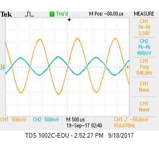
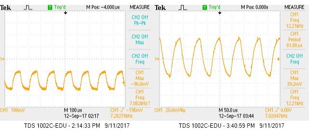
Below is the oscilloscope waveform for two different frequencies from the treasure board. The voltage for these waveforms is taken at the anolog input to the arduino, therefore, it represents the voltage across the resistor in our infrared sensor circuit.

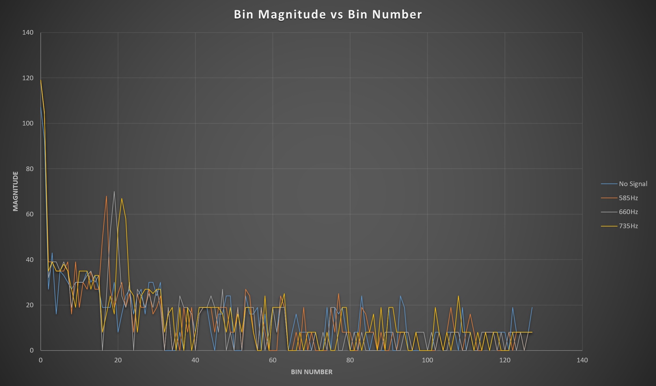
Below is a graph of the corresponding frequency components for each signal. We included an FFT for data which was recorded with no treasure signal. This is useful to tell what the background IR signal is like.

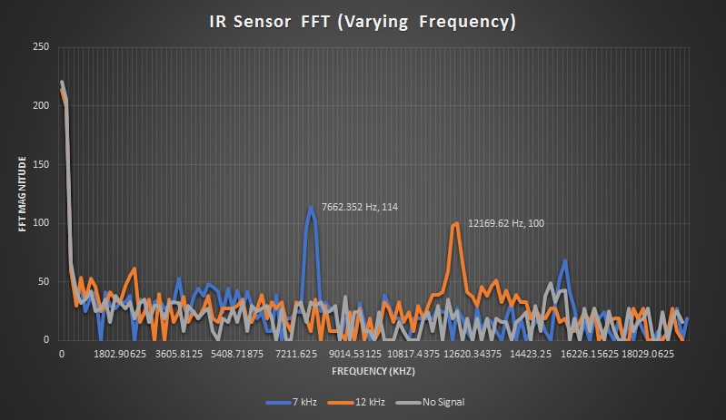
From these FFT's, it is easy to distinguish which signal corresponds to the 7 KHz treasure, and which one corresponds to the 12 KHz signal. For all signals, there is a large DC component, while most of the higher frequency components remain under 50. The two larger peaks at 7 KHz and 12 KHz shows that these two signals have a large contribution from these frequencies.

Once we were able to see the effect of varying signal frequencies on the FFT, we decided to investigate how the distance to the treasure affected the FFT. Below is another FFT graph showing two separate signals. The first signal was taken with the treasure approximately 2 inches from the sensor while the second signal was taken with the treasure approximately 7 inches from the sensor.

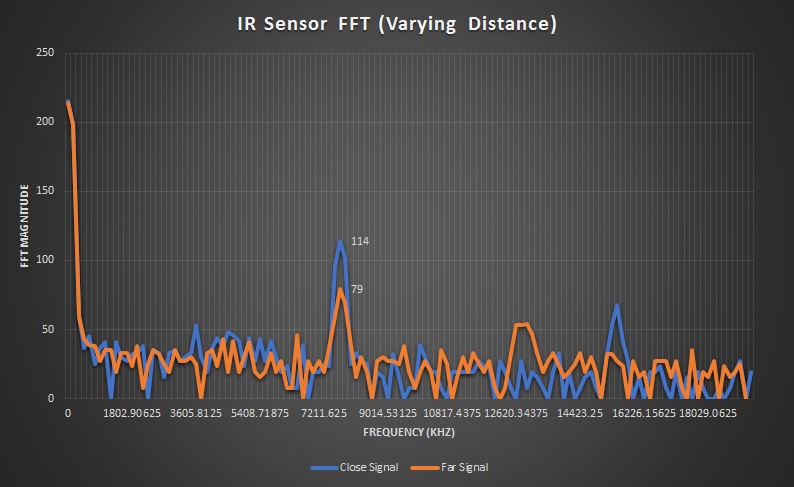
While there is still a peak at 7 KHz, the farther signal is much weaker, and the peak is harder to distinguish.