Milestone 1
ECE 3400 Team 2 Fall 2017
Goal
The purpose of this milestone was to start integrating sensors that output relevant data for our robot to respond to. Using line sensors, our goal was to program our robot to follow black lines of tape as well as trace a figure eight on a grid of black tape. In order to implement this functionality, we needed to understand the type of data outputed from the sensors and properly use it to determine whenever our robot was no longer centered on the black line or was crossing an intersection on a grid.
Materials Used
- 1 Arduino Uno
- 1 USB A/B Cable
- 2 Continuous Rotation Servo
- 4 line sensors
- 1 9Volt Battery
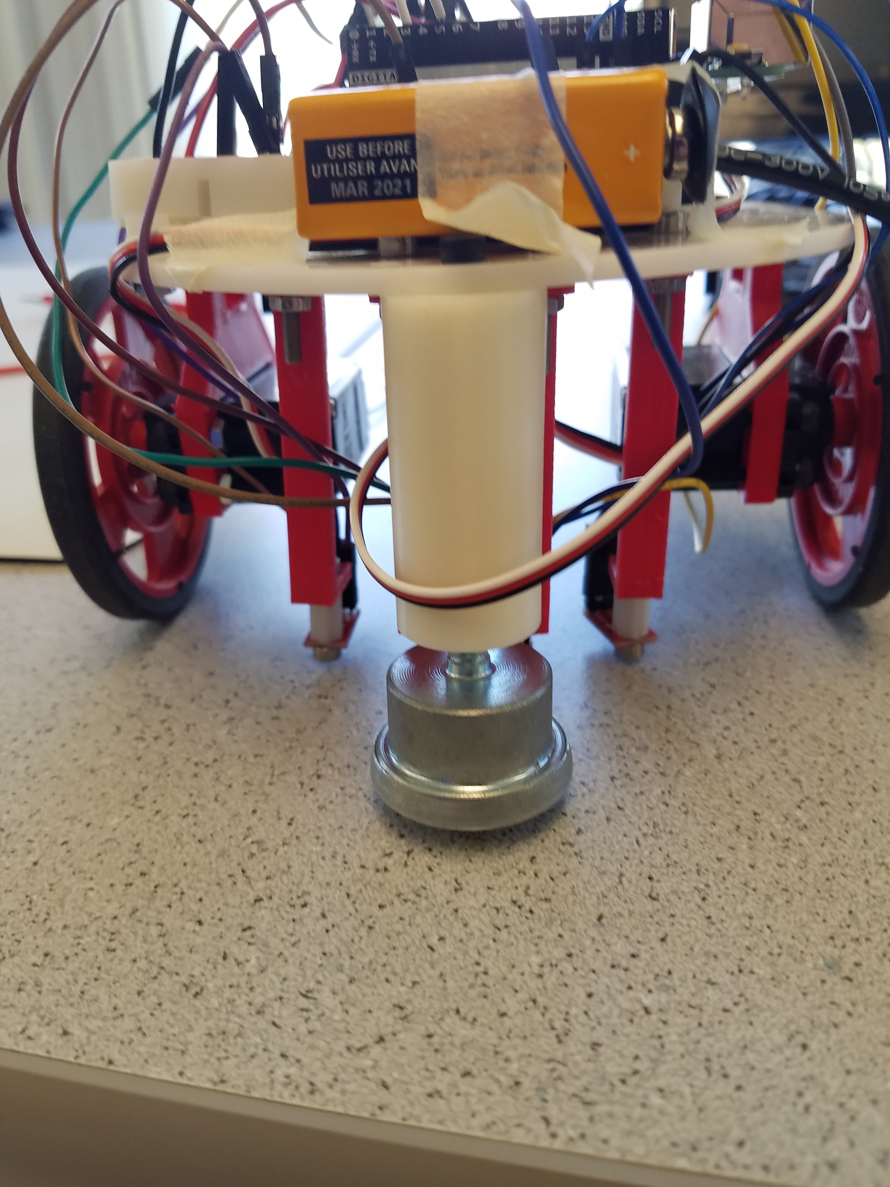
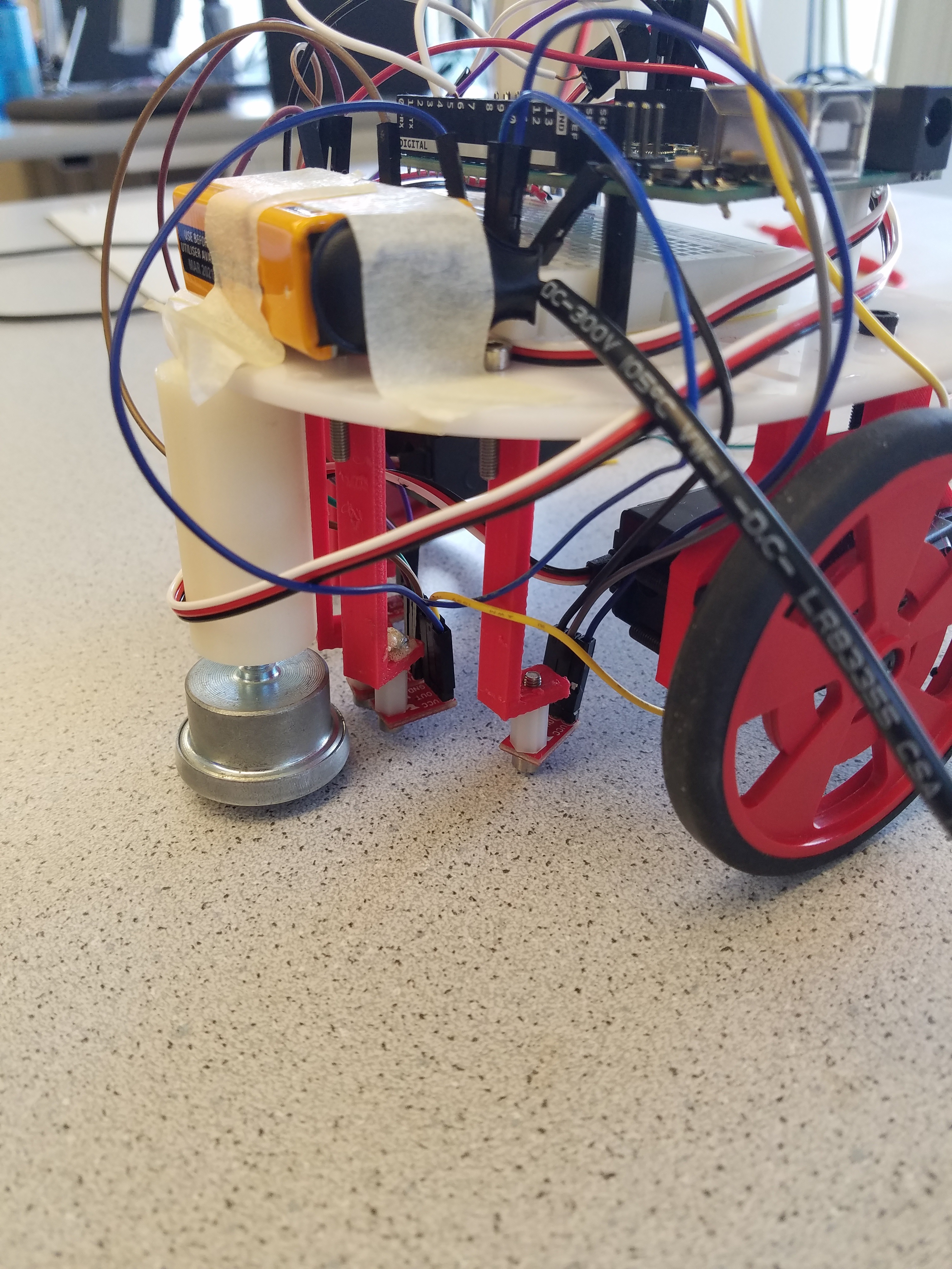
The following images show the current state of our robot. The 4 line sensors are mounted in the front, very close to the ground. We found that these sensors need to be only a few millimeters away to give the most accurate data. The battery, arduino, and breadboard with the necessary wiring are all mounted on the top of our robot.
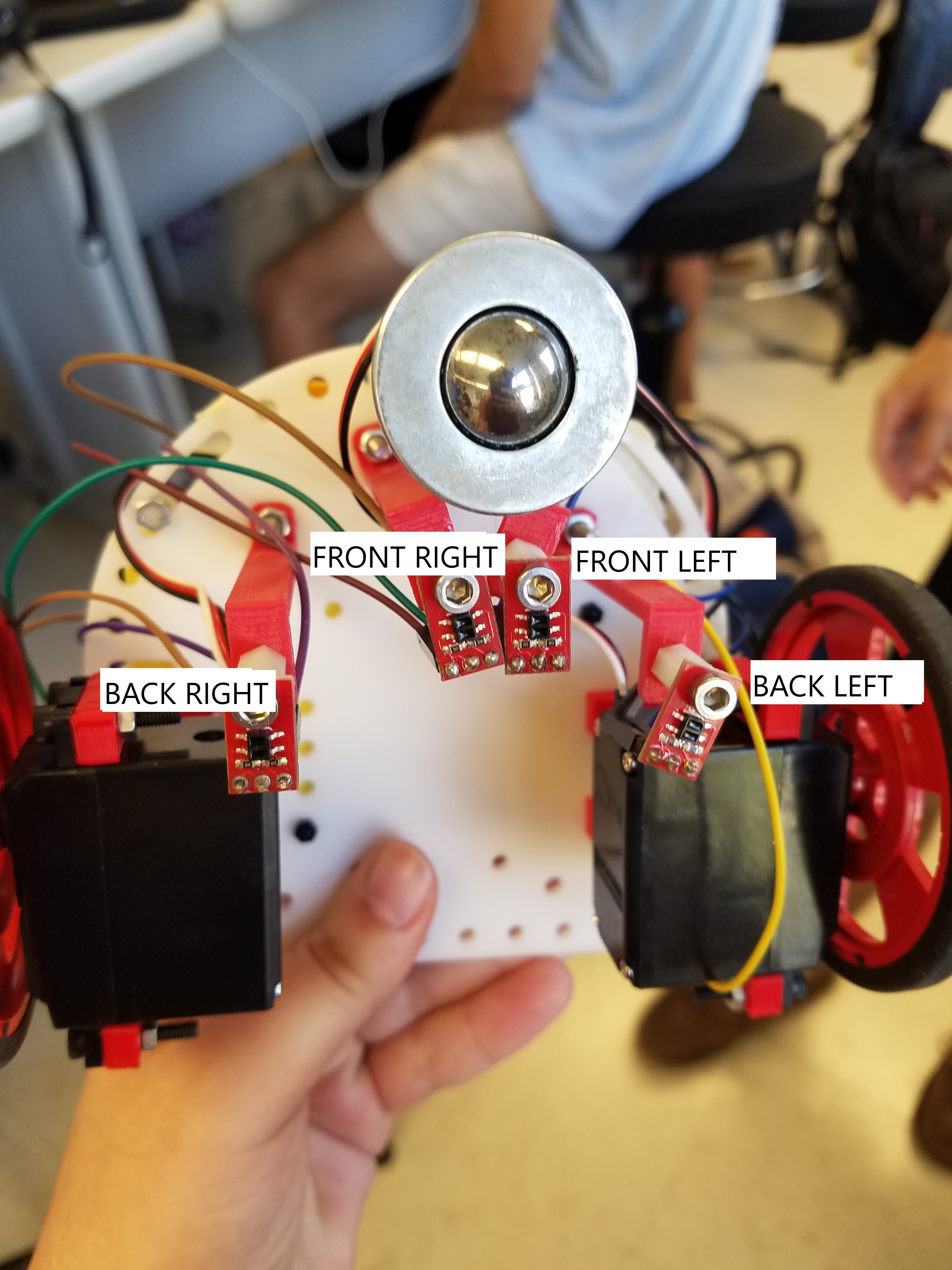
Below you can see the positioning of our 4 line sensors. The middle two (referred to as the front left and front right sensor) are used for line following and should always be over a black line unless in the middle of a turn. The outer two sensors (referred to as the back left and right sensors) are used to detect junctions in the grid.
Line Sensors
The line sensors added to our robot are small infra-red sensors that produce values between 0 and 1000. These values represent a grey scale. If the values are close to zero, then the sensor is detecting a white surface. If the values are close to 1000, then the sensor is detecting a black surface. These sensors are important when trying to follow a grid made of black tape.
Line Following
In order to follow a black line of tape we check the two middle sensors depicted earlier. If the front right sensor is not on the black line, but the front left is, we correct towards the left. If the front left sensor is not on the black line, but the front right is, we correct towards the right. If they are both on the black line we simply continue moving forward.
Figure Eight Algorithm
The main loop portion of our figure eight code involves a series of turns on the grid. First the robot moves forward until a junction is detected. Then the robot turns left and moves forward until another junction is detected. This is followed by four right turns and 3 left turns on the grid. This is repeated with each main loop iteration. To complete this algorithm we needed to implement functions to turn right, turn left, detect junctions, line follow and step past junciton. These functions and their purpose are described in more detail below. In the future we would like to implement this portion of the code using three states: Start, Forward, and Junction. For now we simply have the figure eight code that makes multiple calls to each function written out in the loop section.
Turning
Our turn functions allow us to turn off of one black line and onto anther. To turn, we set the servos to move in opposite directions. Since they are mounted opposite each other, we actually need to set the servos to the same value. For left turns, the servos get set to 180, for right turns 0. We turn until the robot has returned to another black line. We do this by first ensuring that both the front left and right line sensors are no longer reading high values, meaning we have turned off of the black line. We found that we needed this portion of the code because without it, the sensors would immediatley detect that we were on a black line and continue without turning. After moving off the line, we turn until both of the front two line sensors detect another line. We then stop both wheels.
                            void turnRight(){
                                leftWheel.write(180);
                                rightWheel.write(180);
                                //read the line sensors
                                int FR = analogRead(FRlinepin);
                                int FL = analogRead(FLlinepin);
                                //Turn until we are no longer on the black line.
                                while(FR > 800 || FL > 800) {
                                    FR = analogRead(FRlinepin);
                                    FL = analogRead(FLlinepin);
                                }
                                //Turn until we have reached another black line.
                                while(FR < 800 || FL < 800) {
                                    FR = analogRead(FRlinepin);
                                    FL = analogRead(FLlinepin);
                                }
                                leftWheel.write(90);
                                rightWheel.write(90);
                            }
Detecting Junctions
The detect junction function returns true if our robot registers an intersecting black line and false otherwise. If both the back right and left line sensors are producing high values, then they are detecting a new black line and a junction is detected.
                            bool detectJunction(){
                                //read back right and left sensors
                                int BR = analogRead(BRlinepin);
                                int BL = analogRead(BLlinepin);
                                //return true if they both detect a black line
                                if (BL>800 && BR>800){
                                    return true;
                                }
                                else{
                                  return false;
                                }
                            }
Moving Forward
In order to move forward, we first check the front two line sensors. If the front right sensor produces a low value and the left sensor still detects the line, then we know we are vearing right. If the opposite occurs, then we are vearing left. In order to correct this vearing, we stop one wheel so that the robot moves back towards the line. If we are vearing left, we stop the right wheel, if we are vearing right, we stop the left wheel. If both sensors are showing high values, meaning we are positoned properly on the line, we continue moving forward. "left" and "right" are global variables that are initialized at 180 and 0 respectively. Those values correspond to the maximum forward speed of the wheels.
                            void moveForward(){
                                //Front Right Line Sensor Value
                                int FR = analogRead(FRlinepin);
                                //Front Left Line Sensor Value
                                int FL = analogRead(FLlinepin);

                                if (FR > 800 && FL < 800) {
                                  right = 90;
                                }
                                else if (FR < 800 && FL > 800) {
                                  left = 90;
                                }
                                else {
                                  right = 0;
                                  left = 180;
                                }
                                Serial.println(FR);
                                leftWheel.write(left);
                                rightWheel.write(right);
                            }
Step Past Junction
Our team implemented this function to optimize turning. We noticed that our axis of rotation did not perfectly line up with the center of the junction. We were turning just slightly prematurely and this would cause our robot to not line up perfectly on the new black line. Our line following function would correct the issue, but we wanted our robot to turn more smoothly.
We realized the issue was due to the fact that our back line sensors (the ones used to detect the junction) are slightly in front of our center of rotation, not in line with it. This meant that we detected the junction and turned a bit too early. To fix this, we wanted our robot to turn after the back left and right sensors had left the back line. This would line up our center of rotation with the center of the junction. After we detect a junction, this function is called and moves the robot forward until both of the back line sensors detect white instead of black, meaning they have moved past the black line.
                            void stepPastJunction() {
                                leftWheel.write(180);
                                rightWheel.write(0);
                                int BR = analogRead(BRlinepin);
                                int BL = analogRead(BLlinepin);
                                while(BR > 800 || BL > 800) {
                                  BR = analogRead(BRlinepin);
                                  BL = analogRead(BLlinepin);
                                }
                            }
Much of the above code was developed after much trial and error. The initial iteration of our program simply used delays to turn the robot rather than relying on sensor data. Besides this being extremely annoying to get the right delay value, this solution is not terribly robust. If the battery supplying power to the robot has a different voltage, the speed of the turns will be different, and the entire program will be incorrect. As you will notice in our above code, there are no calls to delay();. All of our code is dependant on the sensor data. Therefore, the robot will be able to successfully complete its task even when a number of outside variables change.