Robot Design
ECE 3400 Team 2 Fall 2017
Goal
We were asked to design and build a robot capable of traversing and mapping a maze autonomously, starting after a 660 Hz audible tone is played. The robot also needed to communicate maze information back to a base station, which displayed the maze on a VGA display. When the robot finished traversing the maze, we needed to display a done signal on the VGA display and play a done signal through a set of lab speakers. The maze consisted of a 4x5 grid marked with black tape lines which the robot needed to follow, using line sensors. The grid was surrounded by wooden walls and had some interior walls to form the maze. All walls needed to be detected using short range wall sensors so that the robot could collect data about the walls and avoid running into them. Lastly, there could be various IR treasures placed throughout the maze, which each emit a frequency of either 7kHz, 12kHz, or 17kHz. To detect these, the robot used IR sensors. The base station needed to receive information from the robot wirelessly and display the proper image on the monitor. The proper image needed to include: the robot's current position, unvisited positions, already visited positions, walls, locations of IR treasures (frequency of the treasures needed to be distinguishable), and the visual done signal when ready. Our robot competed with other robots to complete the task. With this in mind, we wanted to not only make it accurate, but also fast. To achieve this, we needed to optimize the physical design of the robot, as well as the code and maze traversing algorithm, as much as we could.
Robot Setup
The final version of our robot included the following components:
- 2 Continous Rotation Servos attached to the two wheels
- 4 line Sensors
- 3 short range IR Wall Sensors
- 3 IR Treasure Sensors
- 1 Arduino Uno
- 1 Microphone
- 1 Eight to One Multiplexer
- 1 Push Button
- 1 Radio
- 1 5V Power Bank
The four line sensors, used to line follow, were placed just a few centimeters above the ground in the front of our robot. Below is a picture of the labeling each of the line sensors.
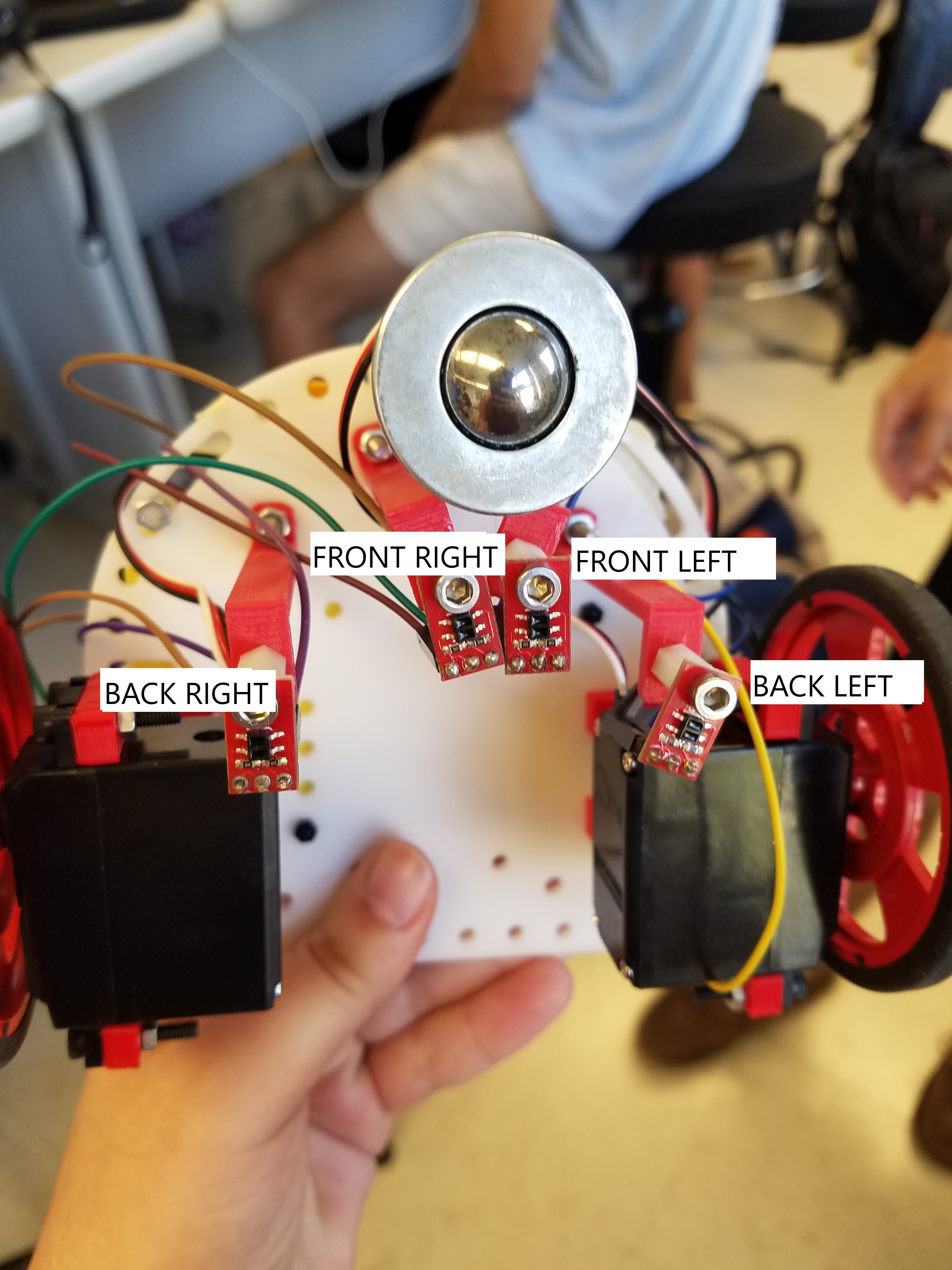
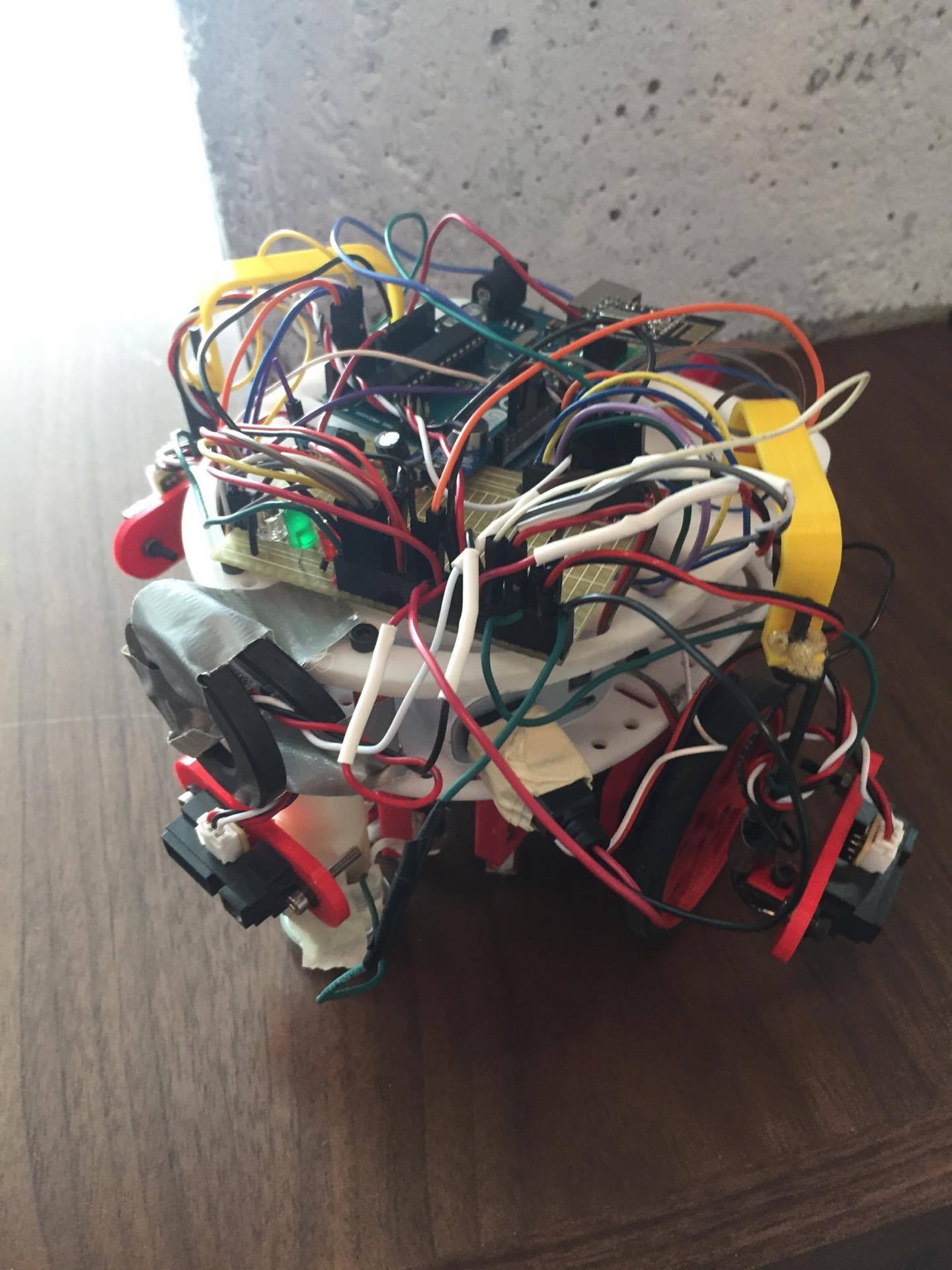
The short range IR sensors are placed on the front and sides of the robot to detect walls in front of, to the right of, or to the left of the robot while it is traversing the maze. The 3 IR treasure sensors are also placed on the front and sides of the robot to detect treasures. Pictured below is our final version of our robot.
| Select Bits | Input Number | Sensor Output |
|---|---|---|
| 000 | Y0 | Left Wall Sensor |
| 001 | Y1 | Front Wall Sensor |
| 010 | Y2 | Right Wall Sensor |
| 011 | Y3 | Microphone |
| 100 | Y4 | Left Treasure Sensor |
| 101 | Y5 | Front Treasure Sensor |
| 110 | Y6 | Right Treasure Sensor |
| 111 | Y7 | Empty |
Towards the end of the semster, as more and more boards and sensors were placed on our robot, we realized we had a weight issue. Our robot's weight was concentrated too far back and would cause the front of our robot to pop up every time it accelerated from a stop. To counteract this, we added washers the front of our robot. In the future we would have liked to clean up this design. If given more time, we would have designed a printed circuit board (PCB) to clean up wiring. This would have allowed us to use just a single level chasis, also taking care of our weight distrubution issue.
Initialization
Before we begin discussing the details of our algorithm, we will first lay out the variable declarations as well as particular initializations used in the setup section of our code. We kept track of our maze using a 5 by 4 array of one byte characters. Each character corresponds to the information about one square in the maze. We use maze[current_row][current_column] to index into the array and access the information about a square. Each bit in the character represents a certain characteristic of that square as follows:
| bit 7 | bit 6 | bit 5 | bit 4 | bit 3 | bit 2 | bit 1 | bit 0 |
|---|---|---|---|---|---|---|---|
| Treasure bit 1 | Treasure bit 0 | visited | unreachable | West wall present | South wall present | East wall present | North wall present |
                                #define NORTHWALL 0x01
                                #define SOUTHWALL 0X02
                                #define EASTWALL 0x04
                                #define WESTWALL 0x08
                                #define UNREACHABLE 0x10
                                #define VISITED 0x20
                                #define SEVEN_TREASURE 0x40
                                #define TWELVE_TREASURE 0x80
                                #define SEVENTEEN_TREASURE 0xc0
In order to keep track of the current direction the robot is facing, we used an enumeration with values north, south, east and west. North corresponds to the direction we place the robot down in originally and the direction is initalized as such.
Our algorithm also needs a way to keep a backtrack queue whenever the robot reaches a square with no more possible unvisited squares to move to. We use an array of size 20 to store our backtrack queue which is comprised of directions to move in if we must backtrack. An int, backtrack_pointer, is used to index into the correct value in this array. A 5 by 4 array of ints is used to mark reachable squares that are still unvisited and is used to tell when our robot has finished mapping the entire maze. This array is called possible_moves_maze.
The setup function of our code initialzes all the pins used as well the servos. For the competition, every robot started in the bottom right corner of the maze so the current row and current column were initialzed to 4 and 3 respectively (the row and column values begin at 0). We also initialize maze[4][3] to be visited and to have a south wall, since we know our robot will be starting with a wall directly behind it.
Algorithm
                            void loop() {
                                  // Don't start until tone or button
                                  while (1) {
                                    if(detect_tone()){
                                      break;
                                    }
                                    if (digitalRead(BUTTON) == HIGH) {
                                      break;
                                    }
                                  }
                                  update_node();
                                  //keep updating until done
                                  while (onward() != -1) {
                                    update_node();
                                  }
                                  //Done
                                  while(1){
                                    transmit_node(maze[current_row][current_column], 255,255);
                                  }
                            }
The detect_tone() function uses the FFT library which outputs values for each bin number. In a previous lab we chose to iterate through 256 bins, but in order to save memory on the arduino, we reduced this amount to 128 bins. By printing out the values of each bin, we found that the 660Hz tone now caused a peak in bin 15. We check if this bin contains a value over 75 to determine if the tone is being played.
                            bool detect_tone() {
                              //Set the MUX select bits
                              digitalWrite(s0, HIGH);
                              digitalWrite(s1, HIGH);
                              digitalWrite(s2, LOW);
                              cli();
                              //Run the FFT
                                for (int i = 0 ; i < 256 ; i += 2) {
                                  fft_input[i] = analogRead(A0);
                                  fft_input[i+1] = 0;
                                }
                                fft_window();
                                fft_reorder();
                                fft_run();
                                fft_mag_log();
                                sei();
                              //Check bin 15
                              if (fft_log_out[15]>75) {
                                return true;
                              }
                              return false;
                            }
The update_node() function checks all the walls around the robot when it is at a junction and updates the corresponding bits in the maze array. The function also checks for treasures and then transmits the fully updated byte of information along with the current row and current column of the robot to the base station.
                            void update_node() {
                            //Update all walls
                              switch(dir) {
                                case(north):
                                  if (left_wall()) { maze[current_row][current_column] |= WESTWALL; }
                                  if (front_wall()) { maze[current_row][current_column] |= NORTHWALL; }
                                  if (right_wall()) { maze[current_row][current_column] |= EASTWALL; }
                                  break;
                                case(south):
                                  if (left_wall()) { maze[current_row][current_column] |= EASTWALL; }
                                  if (front_wall()) { maze[current_row][current_column] |= SOUTHWALL; }
                                  if (right_wall()) { maze[current_row][current_column] |= WESTWALL; }
                                  break;
                                case(east):
                                  if (left_wall()) { maze[current_row][current_column] |= NORTHWALL; }
                                  if (front_wall()) { maze[current_row][current_column] |= EASTWALL; }
                                  if (right_wall()) { maze[current_row][current_column] |= SOUTHWALL; }
                                  break;
                                case(west):
                                  if (left_wall()) { maze[current_row][current_column] |= SOUTHWALL; }
                                  if (front_wall()) { maze[current_row][current_column] |= WESTWALL; }
                                  if (right_wall()) { maze[current_row][current_column] |= NORTHWALL; }
                                  break;
                              }
                                //Check for treasures
                                int treasure = detect_treasure();
                                treasure = treasure << 6;
                                maze[current_row][current_column] |= treasure;
                                //Send the data to the base station
                                transmit_node(maze[current_row][current_column], current_row, current_column);
The functions used to detect walls (left_wall(), front_wall(), and right_wall()), all follow the same structure with the only difference being which mux select signals to set high or low. The wall sensors work by sending values betweeon 0 and 1023 with higher numbers corresponding to closer objects being detected. We found that a threshold of 250 worked well for determining if a wall was detected or not. Below is one of the three wall detection functions:
                            bool left_wall() {
                                  digitalWrite(mux_s2, LOW);
                                  digitalWrite(mux_s1, LOW);
                                  digitalWrite(mux_s0, LOW);

                                  int wall = analogRead(mux_pin);

                                  if (wall>250) {
                                    return true;
                                  }
                                  else {
                                    return false;
                                  }
                                }
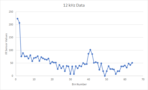
The detect_treasure() function is similar to the detect_tone() function in that it also uses the FFT library. The main difference is that the sampling frequency must be changed since the default is too slow to detect the treasure frequencies of 7kHZ, 12kHz, and 14kHz. In order to speed up the sampling frequency, you must read the value directly from the ADC. The sampling frequency can then be changed by changing the clock prescalar for the ADC clock. By default, the ADC clock is 16 MHz with a default prescalar of 128. Therefore, the ADC clock is 16 MHz/128 = 125 KHz. Since a conversion takes 13 ADC clock cycles, the default sample rate is 125 KHz/13 = 9600 Hz. This sampling rate is not quite fast enough for our purpose, so we adjusted the prescalar to 64 to produce a sampling frequency of approximmately 19.2 KHz. In order to do this, we set the ADPS register to 110. Note, the detect_treasure() function adjusts the ADC clock prescalar as described, but first stores all the changed registers in temporary values so that they can be reset at the end of the function. If we do not do this, we will not be able to use the analogRead() function throughout the rest of our code. Since we also decreased the number of bins from 128 to 256 as we did in the microphone code, we needed to change the bin numbers we checked. Below is an image of the FFT values plotted as a function of bin number when a 12 kHz treasure is present. We used these plots to determine the bin numbers to check for all desired treasure frequencies.
                            int detect_treasure() {
                                  char TIMSK0_temp = TIMSK0;
                                  char ADCSRA_temp = ADCSRA;
                                  char ADMUX_temp = ADMUX;
                                  char DIDR0_temp = DIDR0;
                                  TIMSK0 = 0; // turn off timer0 for lower jitter
                                  ADCSRA = 0xe5; // set the adc to free running mode
                                  ADCSRA &= ~(bit (ADPS0) | bit (ADPS1) | bit (ADPS2)); // clear prescaler bits
                                  ADCSRA |= bit (ADPS0) | bit (ADPS2);
                                  ADMUX = 0x40; // use adc0
                                  DIDR0 = 0x01; // turn off the digital input for adc0

                                  int treasure = 0;
                                  digitalWrite(s2, HIGH);
                                  //iterate through the different treasure sensors on the mux
                                  for (int i = 0; i < 3; i++) {
                                    digitalWrite(s0, LOW);
                                    digitalWrite(s1, LOW);
                                    if (i & 1) {
                                      digitalWrite(s0, HIGH);
                                    }
                                    if (i & 2) {
                                      digitalWrite(s1, HIGH);
                                    }
                                    cli();  // UDRE interrupt slows this way down on arduino1.0
                                    for (int i = 0 ; i < 256 ; i += 2) { // save 256 samples
                                      while(!(ADCSRA & 0x10)); // wait for adc to be ready
                                      ADCSRA = 0xf5; // restart adc
                                      byte m = ADCL; // fetch adc data
                                      byte j = ADCH;
                                      int k = (j << 8) | m; // form into an int
                                      k -= 0x0200; // form into a signed int
                                      k <<= 6; // form into a 16b signed int
                                      fft_input[i] = k; // put real data into even bins
                                      fft_input[i+1] = 0; // set odd bins to 0
                                    }
                                    fft_window(); // window the data for better frequency response
                                    fft_reorder(); // reorder the data before doing the fft
                                    fft_run(); // process the data in the fft
                                    fft_mag_log(); // take the output of the fft
                                    sei();

                                    int seven = fft_log_out[24] + fft_log_out[25];
                                    int twelve = fft_log_out[40] + fft_log_out[41] + fft_log_out[42];
                                    int seventeen = fft_log_out[57] + fft_log_out[58] + fft_log_out[59];

                                    //determine if a treasure is present
                                    if (seven > 120){
                                      treasure = 1;
                                    }
                                    else if (twelve > 180){
                                      treasure = 2;
                                    }
                                    else if (seventeen > 180){
                                      treasure = 3;
                                    }
                                  }
                                  TIMSK0 = TIMSK0_temp;
                                  ADCSRA = ADCSRA_temp;
                                  ADMUX = ADMUX_temp;
                                  DIDR0 = DIDR0_temp;
                                  return treasure;
                                }
The transmit node function is discussed later on in the radio section. The onward() function calls other functions to determine if the robot is done or, if not, what the next move should be. Below is the onward() function.
                            int onward() {
                                  int next = next_move();
                                  if (next == north) { move_north(); }
                                  else if (next == south) { move_south(); }
                                  else if (next == east) { move_east(); }
                                  else if (next == west) { move_west(); }
                                  return next;
                                }
Each of the four possible moving functions (move_north(), move_south(), move_east(), and move_west()) determine, based on the current robot direction, how many left or right turns to make and then move the robot forward until reaching the next junction. Those functions also update the robots direction, the backtrack queue, the backtrack pointer and the maze array with the correct values. Below is the function for move_north(). You will notice the opposite direction, south, is added to the backtrack queue. This is so that when we are backtracking, we simply have to iterate through the array, moving in the direction that is stored in order to move backwards.
                            void move_north() {
                                  switch (dir) {
                                    case(north):
                                      move_forward();
                                      break;
                                    case(south):
                                      turn_left();
                                      turn_left();
                                      move_forward();
                                      break;
                                    case(east):
                                      turn_left();
                                      move_forward();
                                      break;
                                    case(west):
                                      turn_right();
                                      move_forward();
                                      break;
                                  }
                                  dir = north;
                                  current_row -= 1;
                                  maze[current_row][current_column] |= VISITED;
                                  possible_moves_maze[current_row][current_column] = 0;
                                  if(backtracking==false){
                                    backtrack_pointer +=1;
                                    backtrack[backtrack_pointer] = south;
                                  }
                                  else{
                                    backtrack_pointer -= 1;
                                  }
                                  backtracking = false;
                                }
The next_move() function determines which of these functions to call by identifying which directions the robot can move in order to reach an unvisited node that is not blocked by a wall. The possible_moves array stores which direction (north, south, east or west) is a possible move to an unvisited node. Every possible move to an unvisited node is added to the possible_moves array so that we can keep track of when the robot has finished mapping the maze. If there is not a reachable unvisited node, then the last element of possible_moves is set to one to signify that the robot needs to backtrack.
                            int next_move() {
                                  int possible_moves[5] = {0, 0, 0, 0, 0};
                                  int num_moves = 0;
                                  if((!(maze[current_row][current_column] & NORTHWALL)) && (!(maze[current_row-1][current_column] & VISITED))){
                                    possible_moves[north] = 1;
                                    possible_moves_maze[current_row-1][current_column] = 1;
                                    num_moves += 1;
                                  }
                                  if((!(maze[current_row][current_column] & SOUTHWALL)) && (!(maze[current_row+1][current_column] & VISITED))){
                                    possible_moves[south] = 1;
                                    possible_moves_maze[current_row+1][current_column] = 1;
                                    num_moves += 1;
                                  }
                                  if((!(maze[current_row][current_column] & EASTWALL)) && (!(maze[current_row][current_column+1] & VISITED))){
                                    possible_moves[east] = 1;
                                    possible_moves_maze[current_row][current_column+1] = 1;
                                    num_moves += 1;
                                  }
                                  if((!(maze[current_row][current_column] & WESTWALL)) && (!(maze[current_row][current_column-1] & VISITED))){
                                    possible_moves[west] = 1;
                                    possible_moves_maze[current_row][current_column-1] = 1;
                                    num_moves += 1;
                                  }
                                  if (num_moves == 0) {
                                    possible_moves[4] = 1;
                                  }
                                  int next_move = best_move(possible_moves);
                                  return next_move;
                                }
To determine the best move, the best_move() function first checks if the robot is done mapping the maze. If we need to backtrack but the possible_moves array shows only zeros, then the robot is done. Otherwise, the robot iterates through the backtrack queue, moving in the direction stored in the array. If the robot is not backtracking, then we always choose the best move to be in the same direction as the current robot direction if possible. If not then the robot turns right. If the robot can't turn right, it turns around (which should never actually happen since the node behind us should be already visited.) If it doesn't turn around, then it turn lefts.
                            int best_move(int *possible_moves) {
                                  if (possible_moves[4]) {
                                    backtracking = true;
                                    int done = 1;
                                    for (int x = 0; x < 4; x++) {
                                      for (int y = 0; y < 5; y++) {
                                        if ((possible_moves_maze[y][x])) {
                                          done = 0;
                                        }
                                      }
                                    }
                                    if (done) { return -1; }
                                    int next_move = backtrack[backtrack_pointer];
                                    return next_move;
                                  }
                                  switch (dir) {
                                    case(north):
                                      if (possible_moves[north]) { return north; }
                                      else if (possible_moves[east]) { return east; }
                                      else if (possible_moves[west]) { return west; }
                                      else if (possible_moves[south]) { return south; }
                                      break;
                                    case(south):
                                      if (possible_moves[south]) { return south; }
                                      else if (possible_moves[west]) { return west; }
                                      else if (possible_moves[east]) { return east; }
                                      else if (possible_moves[north]) { return north; }
                                      break;
                                    case(east):
                                      if (possible_moves[east]) { return east; }
                                      else if (possible_moves[south]) { return south; }
                                      else if (possible_moves[north]) { return north; }
                                      else if (possible_moves[west]) { return west; }
                                      break;
                                    case(west):
                                      if (possible_moves[west]) { return west; }
                                      else if (possible_moves[north]) { return north; }
                                      else if (possible_moves[south]) { return south; }
                                      else if (possible_moves[east]) { return east; }
                                      break;
                                  }
                                }
All the above functions make up the core of our algorithm in determining where to go at each junction and keeping track of all relevent information. These functions individually work well, but certain fucntions, such as the detect_tone() and detect_treasure() fucntions experience issues when incorporated into our code. These issues, our methods in attempting to resolve them and how we would fix them in the future is dicussed in the Unresolved Issues section below.
Moving Functions
While the previous functions dealt with the logic of our algorithm, the following functions we will discuss, focus around the physical movement and control of the servos to ensure smooth line following and consistent junction detection. The most important function dealing with the smoothness of our robot is the move_forward() function. The function reads in data from the front and left line sensors to detect whether they are over the black line or not. We found that any value over 800 is consistent with line sensors positioned directly above the black line. If the right one has moved off the line, then we want to adjust by turning left, so we write the right wheel to full speed and stop the left wheel. The opposited occurs if the left line sensor has moved off the line. The robot keeps correcting until both line sensors are over the black line. We strategically placed our front right and left line sensors separated by the width of the tape so that we immediately detect any vearing off the line and correct it. The move forward function also continues the movement until a junction is detected and then proceeds to step slightly past the junction. It is important to note that, since the wheels servos are mounted in a mirrored fashion, the values written to the servos to move forward at maximum speed are oposite (0 for the right wheel and 180 for the left). Both wheels stop when written to a value of 90. Below is the move forward function.
                            void move_forward() {
                                  while (!detect_junction()) {
                                    int fr = analogRead(fr_linepin);
                                    int fl = analogRead(fl_linepin);

                                    if (fr > 800 && fl < 800) {
                                      right_pwm = 90;
                                    }
                                    else if (fr < 800 && fl > 800) {
                                      left_pwm = 90;
                                    }
                                    else {
                                      right_pwm = 0;
                                      left_pwm = 180;
                                    }
                                    right_wheel.write(right_pwm);
                                    left_wheel.write(left_pwm);
                                  }
                                  step_past_junction();
                                }
The detect_junction() function simply reads the values of the back right and back left line sensors and returns true if they are ever over 800, meaning they have detected a black line. The positioning of the back right and left line sensors is also imperative. They must be far enough away from the middle as to not detect a junction if the robot vears slightly off the black line. Below is the detect_junction() function:
                            bool detect_junction() {
                                  int br = analogRead(br_linepin);
                                  int bl = analogRead(bl_linepin);
                                  if (br > 800 && bl > 800) {
                                    Serial.println("detect junction");
                                    return true;
                                  }
                                  return false;
                                }
The step_past_junction() function moves the robot forward past a junction until the back right and left line sensors are no longer over the black line. The purpose of this function is to improve the accuracy of our turning. By stepping past, the robots center of rotation more closely matches the center of the junction, allowing to turn directly over the junction and continue onto the next line more smoothly. The stepping_past_junction() is as follows:
                            void step_past_junction() {
                                  right_wheel.write(0);
                                  left_wheel.write(180);
                                  int br = analogRead(br_linepin);
                                  int bl = analogRead(bl_linepin);
                                  while (br > 800 || bl > 800) {
                                    br = analogRead(br_linepin);
                                    bl = analogRead(bl_linepin);
                                  }
                                  right_wheel.write(90);
                                  left_wheel.write(90);
                                }
The turning functions, turn_left() and turn_right() simply write values to the wheels to make them move in opposite directions. For example, to turn left, the right wheel is written to 0 in order to move forward and the left wheel is written to 0 in order to move backwards. This allows the robot to turn quickly and in place over the junction. The turn ends when both the front right and left line sensors are over the black line again. Below is the turn_left() function:
                            void turn_left() {
                                  Serial.println("turning left");
                                  left_wheel.write(0);
                                  right_wheel.write(0);
                                  int fr = analogRead(fr_linepin);
                                  int fl = analogRead(fl_linepin);
                                  while (fr > 800 || fl > 800) {
                                    fr = analogRead(fr_linepin);
                                    fl = analogRead(fl_linepin);
                                  }
                                  while (fr < 800 || fl < 800) {
                                    fr = analogRead(fr_linepin);
                                    fl = analogRead(fl_linepin);
                                  }
                                  left_wheel.write(90);
                                  right_wheel.write(90);
                                }
Unresolved Issues and Further Optimization
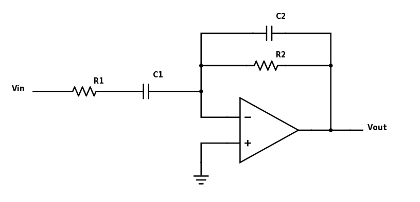
Unfortately, we could not get every facet of our code working together for the final competition. Our microphone code, used to start the robot at the sound of a 660Hz tone, malfunctioned whenever used at the same time as our wall sensors. When simply running the detect_tone() function, we received accurate values with very little noise. However, once the wall sensors were introduced, the values would spike, introducing a lot of noise, making it impossible to detect the tone. We decided to, for the competition, simply start the robot with the push botton. Originally we planned on having an op amp combined with a band-pass filter in order to fix these issues, but, due to time constraints, were never able to. In the future, we would have liked to implement a filter similar to the one shown below:
In order to improve the efficiency of our alogorithm, in the future we would have adjusted the backtracking. A faster way to backtrack to any unvisited nodes is to find the direct path from the current robot location to the closest unvisited node. This would cut down a significant amount of time when mapping the full maze. Another way to optimize the algorithm is to implement something closer to Dijkstra's shortest path algorithm. All reachable nodes would be stored and the closest one to get to would be visited first. This would probably reduce the amount of nodes that we would need to revisit in order to map the entire maze.
In Action
Here is a video of our robot traversing a maze and sending the information to the FPGA!
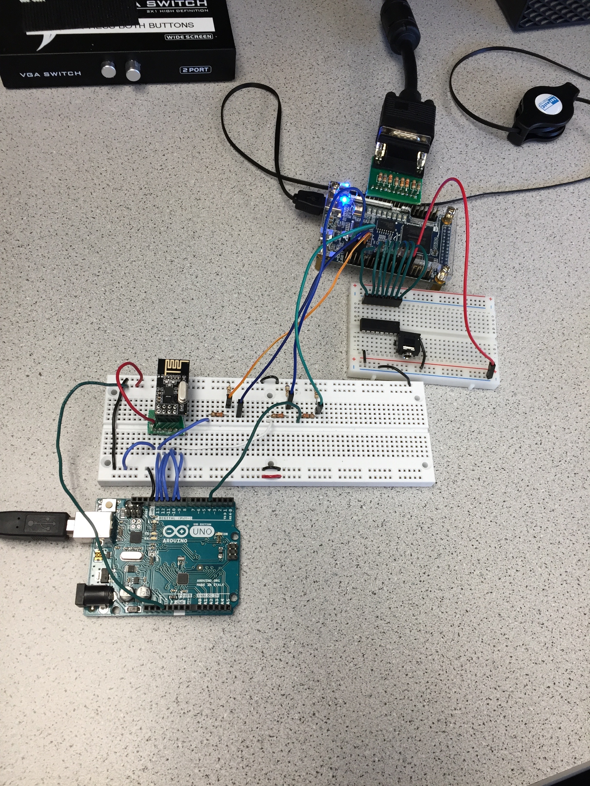
Components of Final Base Station
For the final competition, our base station consisted of the following components:
- 1 Arduino Uno
- 1 Radio
- 1 FPGA DE0-Nano
- 2 8-bit DACs
- 2 Breadboards
- 1 Stereo Jack
- Various Wires and Resistors
Overview of FPGA Functionality
The FPGA was the single most important component of our base station. First, it needed to be able to communicate with our base station's Arduino, which would be receiving maze information from our robot via the wireless radios. Second, it needed to act as the driver for the VGA monitor that we needed to display the maze on. The FPGA also acted as the platform upon which our logic to update the VGA display in real-time was stored. Additionally, the FPGA needed to output an audio tune to the speakers to play when the robot finished mapping the maze.
Communication with Base Station Arduino
As we discussed for Milestone 4, we decided to use the SPI serial communication protocol to facilitate communication between the Base Station Arduino and the FPGA. To recap what was mentioned then, we needed four connection lines between the Arduino and the FPGA: clock (SCK), MOSI (master-out, slave-in), MISO (master-in, slave-out), and slave-select (SS). The SCK, MISO, and MOSI lines were connected to Arduino pins 13, 12, and 11, respectively. We also assigned the SS pin for SPI communication to be digital pin 4 on the Arduino. In order for the Arduino to send data to the FPGA, the SS line needed to be set to low and kept low for the duration of the communication period. Data was sent from the Arduino to the FPGA on the MOSI line. Hence, the Arduino was the master and the FPGA was the slave. Three of the four Arduino pins connected to the FPGA needed to go through a voltage divider first to step the voltage down from 5V (the output voltage of the arduino digital pins) to 3.3V (the input voltage of the GPIO pins on the FPGA) by using 330 Ohm and 680 Ohm resistors. The only line that did not need to go through a voltage divider was the MISO line because its voltage was determined by the GPIO pin on the FPGA that was acting as the output.
An important discovery that we made during testing was that the MISO line was disrupting our radio communication between Arduinos. However, the MISO line was technically never used because we only communicated from Arduino to FPGA, never the other way. Therefore, we ended up disconnecting our MISO line altogether, and its interference with the radio communication ended.
Below is our sequential logic block from our spi_slave.v module on the FPGA:
                        always @(*) begin
                            ss_d = ss;
                            mosi_d = mosi;
                            miso_d = miso_q;
                            sck_d = sck;
                            sck_old_d = sck_q;
                            data_d = data_q;
                            done_d = 1'b0;
                            bit_ct_d = bit_ct_q;
                            dout_d = dout_q;

                            if (ss_q) begin                           // if slave select is high (deselcted)
                              bit_ct_d = 4'b0;                        // reset bit counter
                              data_d = din;                           // read in data
                              miso_d = data_q[15];                     // output MSB
                            end else begin                            // else slave select is low (selected)
                              if (!sck_old_q && sck_q) begin          // rising edge
                                data_d = {data_q[14:0], mosi_q};       // read data in and shift
                                bit_ct_d = bit_ct_q + 1'b1;           // increment the bit counter
                                if (bit_ct_q == 4'b1111) begin         // if we are on the last bit
                                  dout_d = {data_q[14:0], mosi_q};     // output the byte
                                  done_d = 1'b1;                      // set transfer done flag
                                  data_d = din;                       // read in new byte
                                end
                              end else if (sck_old_q && !sck_q) begin // falling edge
                                miso_d = data_q[15];                   // output MSB
                              end
                            end
                        end
As you can see, new information is only read in when the slave select line is low.
The following is our instantiation of spi_slave in our main DE0_NANO.v module that was loaded onto the FPGA for the competition:
                        spi_slave slave(
                            .clk(CLOCK_25),
                            .rst(reset),
                            .ss(GPIO_1_D[32]),
                            .mosi(GPIO_1_D[30]),
                            .miso(GPIO_1_D[28]),
                            .sck(GPIO_1_D[26]),
                            .done(DONE),
                            .din(DIN),
                            .dout(DOUT),
                        );
Our four communication lines were connected to four adjacent GPIO pins, pins 26, 28, 30, and 32 on the GPIO_1 or JP2 side.
Driving VGA Monitor
Like we mentioned in Milestone 4, we chose to subdivide the display into 10 pixel x 10 pixel squares, in order to display a 5x4 maze on the screen. Using this convention, we made the wall widths 10 pixels and all the actual grid spaces 80 pixels x 80 pixels. With five wall spaces and four grid spaces in the x-direction and six wall spaces and five grid spaces in the y-direction, our entire maze takes up a 370 pixel x 460 pixel area on the monitor. The following is the instantiation of our VGA_DRIVER module that we made in DE0_NANO:
                        // Module outputs coordinates of next pixel to be written onto screen
                        VGA_DRIVER driver(
                            .RESET(reset),
                            .CLOCK(CLOCK_25),
                            .PIXEL_COLOR_IN(PIXEL_COLOR),
                            .PIXEL_X(PIXEL_COORD_X),
                            .PIXEL_Y(PIXEL_COORD_Y),
                            .PIXEL_COLOR_OUT({GPIO_0_D[9],GPIO_0_D[11],GPIO_0_D[13],GPIO_0_D[15],GPIO_0_D[17],GPIO_0_D[19],GPIO_0_D[21],GPIO_0_D[23]}),
                            .H_SYNC_NEG(GPIO_0_D[7]),
                            .V_SYNC_NEG(GPIO_0_D[5])
                        );
This VGA_DRIVER module outputs to the VGA monitor like we discussed in Labs 3 and 4. The adjacent GPIO pins between pins 9 and 23 on the GPIO_0 side first connect to the 8-bit DAC that we discussed for Lab 3. The DAC is then connected to the VGA switch via a VGA cable.
The data structure that we used to store the pixel color data for the full 370 pixel x 460 pixel maze was a 37x46 array that we called wall_grid. This data structure stores 3-bit values, which encode what color to assign to each 10 pixel x 10 pixel square. We needed 3-bits because there were 8 possible colors that could be assigned. Our final color scheme was:
- Turqoise = Unvisited/unreachable grid space
- Yellow = Robot's current position
- Magenta = Already visited grid space
- White = No wall
- Black = Wall
- Red = 7 kHz treasure at that grid space
- Green = 12 kHz treasure at that grid space
- Blue = 17 kHz treasure at that grid space
These two blocks in DE0_NANO encode each color to a number between 0 and 7 and store the color data in a vector called colors:
                        reg[7:0] red = 8'b111_000_00;
                        reg[7:0] white = 8'b111_111_11;
                        reg[7:0] blue = 8'b000_000_11;
                        reg[7:0] green = 8'b000_111_00;
                        reg[7:0] black = 8'b000_000_00;
                        reg[7:0] turqoise = 8'b000_111_11;
                        reg[7:0] yellow = 8'b111_111_00;
                        reg[7:0] purple = 8'b111_000_11;

                        assign colors[0] = turqoise; //unvisited or unreachable
                        assign colors[1] = yellow; //current position
                        assign colors[2] = purple; //already visited
                        assign colors[3] = white; //no wall
                        assign colors[4] = black; //wall
                        assign colors[5] = red; //7 kHz treasure
                        assign colors[6] = green; //12 kHz treasure
                        assign colors[7] = blue; //17 kHz treasure
After executing our logic to assign the correct colors to wall_grid, the following lines actually assign the correct colors to the correct pixels on the screen via our instantiation of VGA_DRIVER:
                        newx = PIXEL_COORD_X/10'd10;
                        newy = PIXEL_COORD_Y/10'd10;
                        if (PIXEL_COORD_X > 369 || PIXEL_COORD_Y > 459) begin
                            PIXEL_COLOR = colors[3];
                        end
                        else begin
                            PIXEL_COLOR = colors[wall_grid[newx][newy]];
                        end
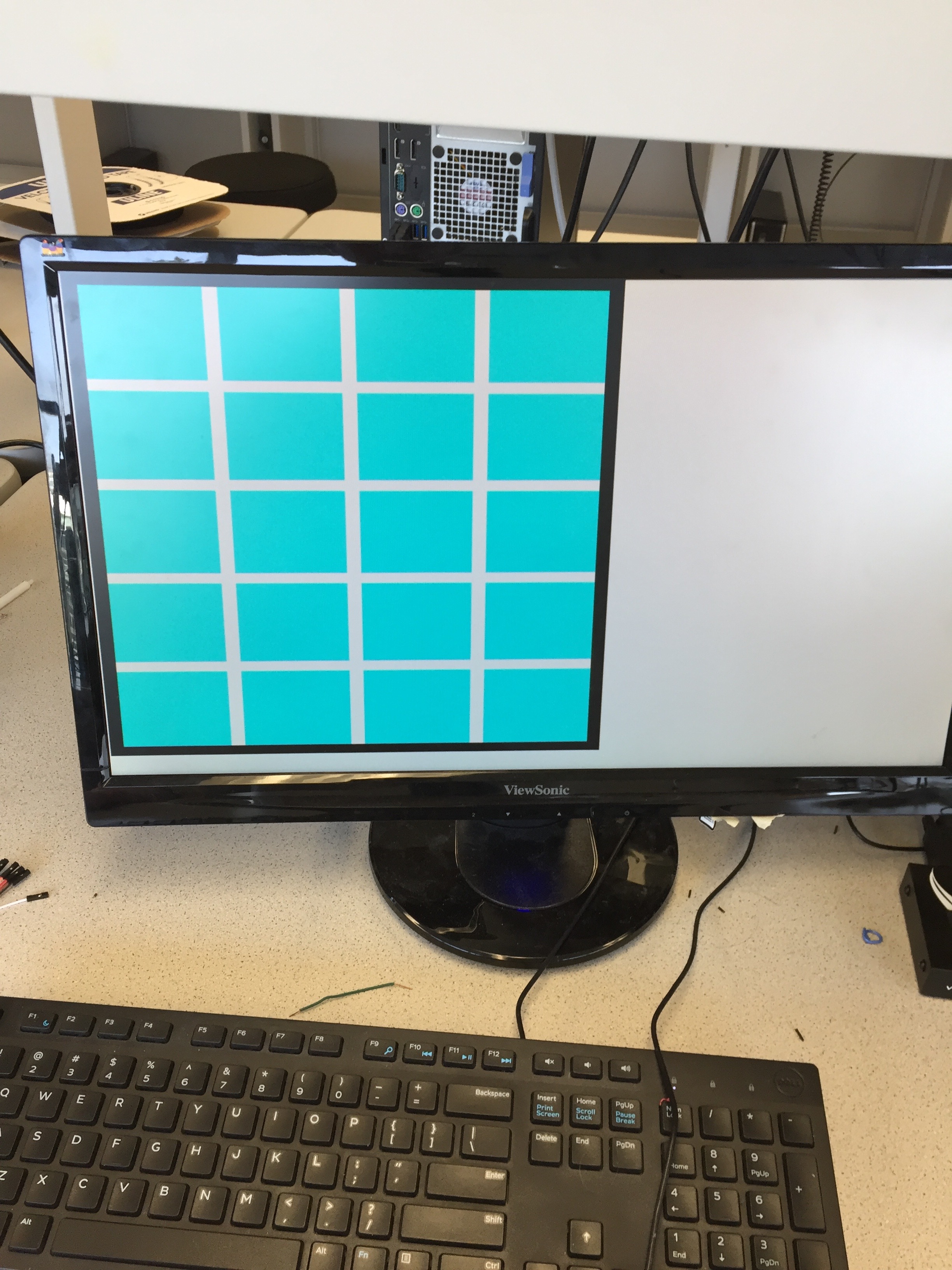
Notice that everything outside the 370x460 pixel range is set to color 3, which is white. Upon start-up or reset, wall_grid is initialized using the following code, which colors everything turqoise and then overlays white for the interior wall positions and black for the perimeter wall positions. This process generates the initialize maze in the picture below:
                        integer i;
                        integer j;

                        for (i = 0; i < 37; i=i+1) begin
                            for (j = 0; j < 46; j=j+1) begin

                                wall_grid[i][j] = 3'b000;

                                if (i%9 == 0) begin
                                    wall_grid[i][j] = 3'b011;
                                end

                                if (j%9 == 0) begin
                                    wall_grid[i][j] = 3'b011;
                                end
                                if (i%36 == 0) begin
                                    wall_grid[i][j] = 3'b100;
                                end
                                if (j%45 == 0) begin
                                    wall_grid[i][j] = 3'b100;
                                end
                                else begin
                                    wall_grid[i][j] = wall_grid[i][j];
                                end
                            end
                        end
Confronting Our Problems
Following Milestone 4, we encountered several issues with the logic in our FPGA code resulting in random pixelation on the VGA display and incorrect locations being colored in. We were able to initialize and color the starting maze correctly, but when we coded the Arduino to send hard-coded instruction values via SPI the problems surfaced. Our grid was colored by having an always @ (*) block with combinational logic assign colors to many small pixel segments. After consulting a TA, we speculated that our problems were caused by unintentionally assigning colors to certain pixels multiple times in the always block.
State Machine and Logic
To fix our problems, we decided to implement a state machine in order to isolate multiple locations in the code where colors were assigned to pixels. Our state machine had 8 states, and the following list indicates the purpose of each state:
- State 000 = Done Mapping/Play Audio
- State 001 = Parse Incoming Data from Arduino
- State 010 = Color Current Location/Mark Treasure
- State 011 = Color West Wall
- State 100 = Color East Wall
- State 101 = Color South Wall
- State 110 = Color North Wall
- State 111 = Color Previous Location
Initialization
To incorporate a state machine effectively, we used sequential logic inside an always block triggered by the positive edge of the 25 MHz clock on the FPGA. Prior to entering the state machine, we needed to initialize the system. We used the following code to do this:
                        always @ (posedge CLOCK_25) begin       // Set always block to posedge CLK
                            if (reset) begin    // Condition for initialization

                                integer i;
                                integer j;

                                for (i = 0; i < 37; i=i+1) begin    // Loop through pixel grid
                                    for (j = 0; j < 46; j=j+1) begin

                                        wall_grid[i][j] = 3'b000;   // Color all unvisited turqoise

                                        if (i%9 == 0) begin         // Color all walls white to start
                                            wall_grid[i][j] = 3'b011;
                                        end

                                        if (j%9 == 0) begin         // Color all walls white to start
                                            wall_grid[i][j] = 3'b011;
                                        end
                                        if (i%36 == 0) begin        // Color perimeter walls black
                                            wall_grid[i][j] = 3'b100;
                                        end
                                        if (j%45 == 0) begin        // Color perimeter walls black
                                            wall_grid[i][j] = 3'b100;
                                        end
                                        else begin                  // To help prevent inferred latches
                                            wall_grid[i][j] = wall_grid[i][j];
                                        end
                                    end
                                end

                                xpos = 3;                           // Initialize starting at bottom right
                                ypos = 4;
                                state = 3'b001;                     // Next state
                                check = 1'b0;
                                LAST_POS = 16'bxxx10011xxxxxxxx;    // Save last position at bottom right
                                doneaudio = 1'b0;                   // Initialize low to not play audio tone
                            end
Notice that the nested for loops are the same ones that we discussed above. In addition to the for loops, we set the robot's current position to the correct starting position in the bottom right corner of the maze, set doneaudio to disabled (to be discussed later), save the current position as the last or previous position for the next cycle, and move to the first state (to be done at the next cycle).
State 001: Parse Incoming Data
In this state, we first check if the DONE signal is set to HIGH, which would indicate the data is ready to be read from the SPI transfer. The actual data is stored in a 16-bit long register titled DOUT. We parse the 16 bits according to the code below.
                        else if (DONE == 1'b1 && state == 3'b001) begin
                            CURR_POS = DOUT;                            // Save data
                            donecheck = (CURR_POS[15:13]);              // Signals when robot is done traversing maze
                            ypos = (CURR_POS[12:10]);
                            xpos = (CURR_POS[9:8]);
                            treasure = CURR_POS[7:6];
                            visited = CURR_POS[5];
                            unreach = CURR_POS[4];
                            wallw = CURR_POS[3];
                            walle = CURR_POS[2];
                            walls = CURR_POS[1];
                            walln = CURR_POS[0];
                            state = 3'b010;                             // Next State

                        end
If DONE is not set to HIGH, we will wait in this state until it is. Finally, we move to the second state.
State 010: Color Treasure and/or Current Location
Before discussing this state, we should mention that we also maintained a secondary data structure in our logic, called data_struc. This structure was a 9x11 array of 3-bit values, which encoded the color of the corresponding grid space or wall. There were 9 horizontal positions because there were 4 grid spaces and up to 5 walls in that direction. Similarly, there were 11 vertical positions because there were 5 grid spaces and up to 6 walls in that direction. We opted to use this data structure because it seemed easier to update correctly when receiving incoming data from the robot. Then, we just needed to create a mapping between the positions in data_struc and the corresponding positions in wall_grid, which is the data structure actually displayed on the VGA monitor. Note that a single position in data_struc always maps to several positions in wall_grid. Each wall position in data_struc maps to 8 positions in wall_grid, while each grid space in data_struc maps to 64 positions in wall_grid. This allowed us to create a more accurate display, with grid spaces appearing larger than walls. The equations to map from a grid space in data_struc to 64 positions in wall_grid were (x' = 9(x-1)/2 + n) and (y' = 9(y-1)/2 + n), where x' and y' are coordinates in wall_grid, x and y are coordinates in data_struc, and n is an offset that sweeps from 1 to 8. This mapping was essential for updating the grid positions correctly.
Now, in this state, we first convert the coordinates for the 4x5 grid received from the robot into coordinates for the 9x11 data_struc. Using the equations shown in the code below, positions 0 through 4 in terms of the robot's 4x5 coordinates would map to positions 1, 3, 5, 7, and 9 in data_struc. This is important because now gaps are left for the wall information to occupy. The code for this state is:
                        else if (state == 3'b010) begin

                            bigy = (ypos << 1) + 1;     // Convert 4x5 positions to 9x11
                            bigx = (xpos << 1) + 1;

                            //Treasure & Current Position
                            if (treasure == 2'b01) begin            //if 7 kHz treasure
                                data_struc[bigx][bigy] = 3'b101;    //Color Red
                            end
                            else if (treasure == 2'b10) begin       //if 12 kHz treasure
                                data_struc[bigx][bigy] = 3'b110;    //Color Green
                            end
                            else if (treasure == 2'b11) begin       //if 17 kHz treasure
                                data_struc[bigx][bigy] = 3'b111;    //Color Blue
                            end
                            else begin                              //if no treasure
                                data_struc[bigx][bigy] = 3'b001;    //color normal yellow for current position
                            end

                            //Grid Space!
                            wall_grid[(9*((bigx-1)>> 1))+1][(9*((bigy-1)>> 1))+1] = data_struc[bigx][bigy];
                            wall_grid[(9*((bigx-1)>> 1))+1][(9*((bigy-1)>> 1))+2] = data_struc[bigx][bigy];
                            wall_grid[(9*((bigx-1)>> 1))+1][(9*((bigy-1)>> 1))+3] = data_struc[bigx][bigy];
                            wall_grid[(9*((bigx-1)>> 1))+1][(9*((bigy-1)>> 1))+4] = data_struc[bigx][bigy];
                            wall_grid[(9*((bigx-1)>> 1))+1][(9*((bigy-1)>> 1))+5] = data_struc[bigx][bigy];
                            wall_grid[(9*((bigx-1)>> 1))+1][(9*((bigy-1)>> 1))+6] = data_struc[bigx][bigy];
                            wall_grid[(9*((bigx-1)>> 1))+1][(9*((bigy-1)>> 1))+7] = data_struc[bigx][bigy];
                            wall_grid[(9*((bigx-1)>> 1))+1][(9*((bigy-1)>> 1))+8] = data_struc[bigx][bigy];

                            // etc...
                            state = 3'b011;                     //Next State
                        end
Notice that we always assign the correct color to data_struc and then map from data_struc to wall_grid. Also, note that we actually have 7 more blocks of 8 assignments to wall_grid where we increment the offset of the first index into wall_grid from 2 to 8. Finally, we move to the third state.
States 011, 100, 101, and 110: Color Walls
In these four consecutive states, we set the wall positions around the robot's current location to the correct colors. States 011, 100, 101, and 110 color the west, east, south, and north walls, respectively. Our code for the west wall state is:
                        else if (state == 3'b011) begin
                            //West Wall
                            if (wallw == 1'b1) begin                    //if wall detected
                                data_struc[bigx-1][bigy] = 3'b100;      //color wall black
                            end
                            else begin                                  //if no wall
                                data_struc[bigx-1][bigy] = 3'b011;      //color position white
                            end

                            wall_grid[9*((bigx-1)>> 1)][(9*((bigy-1)>> 1))+1] = data_struc[bigx-1][bigy];
                            wall_grid[9*((bigx-1)>> 1)][(9*((bigy-1)>> 1))+2] = data_struc[bigx-1][bigy];
                            wall_grid[9*((bigx-1)>> 1)][(9*((bigy-1)>> 1))+3] = data_struc[bigx-1][bigy];
                            wall_grid[9*((bigx-1)>> 1)][(9*((bigy-1)>> 1))+4] = data_struc[bigx-1][bigy];
                            wall_grid[9*((bigx-1)>> 1)][(9*((bigy-1)>> 1))+5] = data_struc[bigx-1][bigy];
                            wall_grid[9*((bigx-1)>> 1)][(9*((bigy-1)>> 1))+6] = data_struc[bigx-1][bigy];
                            wall_grid[9*((bigx-1)>> 1)][(9*((bigy-1)>> 1))+7] = data_struc[bigx-1][bigy];
                            wall_grid[9*((bigx-1)>> 1)][(9*((bigy-1)>> 1))+8] = data_struc[bigx-1][bigy];

                            state = 3'b100;                             //Next State

                        end
Just like when coloring grid spaces, we assign the correct color to the correct position in data_struc first. Then, we assign that color to the corresponding 8 positions in wall_grid that make up one wall. We end by moving to the next state. Note that the next three states for the other walls are implemented in almost the exact same way as this state, and, therefore, we will not discuss them here.
State 111: Color Last Position
After coloring the walls, state 111 colors the robot's previous location, which we originally saved during initialization. The code to accomplish this is:
                        else if (state == 3'b111) begin
                            if (check == 1'b1) begin
                                ylast = (LAST_POS[12:10]);      //coordinates of last position
                                xlast = (LAST_POS[9:8]);

                                lastbigx = (2*xlast) + 1;       //convert to 9x11 format
                                lastbigy = (2*ylast) + 1;
                                data_struc[lastbigx][lastbigy] = 3'b010;    //color Magenta

                                wall_grid[9*((lastbigx-1)/2)+1][9*((lastbigy-1)/2)+1] = data_struc[lastbigx][lastbigy];
                                wall_grid[9*((lastbigx-1)/2)+1][9*((lastbigy-1)/2)+2] = data_struc[lastbigx][lastbigy];
                                wall_grid[9*((lastbigx-1)/2)+1][9*((lastbigy-1)/2)+3] = data_struc[lastbigx][lastbigy];
                                wall_grid[9*((lastbigx-1)/2)+1][9*((lastbigy-1)/2)+4] = data_struc[lastbigx][lastbigy];
                                wall_grid[9*((lastbigx-1)/2)+1][9*((lastbigy-1)/2)+5] = data_struc[lastbigx][lastbigy];
                                wall_grid[9*((lastbigx-1)/2)+1][9*((lastbigy-1)/2)+6] = data_struc[lastbigx][lastbigy];
                                wall_grid[9*((lastbigx-1)/2)+1][9*((lastbigy-1)/2)+7] = data_struc[lastbigx][lastbigy];
                                wall_grid[9*((lastbigx-1)/2)+1][9*((lastbigy-1)/2)+8] = data_struc[lastbigx][lastbigy];

                                //etc...
                                LAST_POS = CURR_POS;            //Save current position to be last position at next cycle
                            end
                            check = 1'b1;
                            if (donecheck == 3'b111) begin      //if robot has sent the done signal
                                state = 3'b000;                 //move to state 000
                            end
                            else begin                          //if robot has not yet finished
                                state = 3'b001;                 //go back to the first state and repeat
                            end
                        end
Note that check is a reg that we initialize to be 0. Hence we do not color the previous location during the first cycle, which makes sense because the robot would still be at the first position. After the first cycle, check is always 1, so we always color the previous location when in this state. Once again, there are actually 7 more blocks of 8 assignments to wall_grid in order to color a complete grid space on the VGA display. We also always save the robot's current position to be the last position at the next cycle. Finally, if the robot has sent the done signal, we move to the final state 000. If not, we move back to state 001 and cycle through all the states again.
State 000: Done and Audio
Once we reach the final state, meaning that the robot has just completed its maze traversal, we first set the outer perimeter of the maze on the display to green, which is our visual done signal. Then, we set doneaudio to 1, which will cause our audible done tune to play. Finally, we set state to 000, so we just stay in this final state.
                        else if (state == 3'b000) begin
                            integer i;
                            integer j;

                            for (i = 0; i < 37; i=i+1) begin
                                for (j = 0; j < 46; j=j+1) begin

                                    if (i%36 == 0) begin
                                            wall_grid[i][j] = 3'b110;       //color outer perimeter Green
                                    end
                                    if (j%45 == 0) begin
                                            wall_grid[i][j] = 3'b110;       //color outer perimeter Green
                                    end
                                end
                            end
                            doneaudio = 1'b1;                               //set audio enable to HIGH
                            state = 3'b000;                                 //stay in this state
                        end
The following video shows how our logic works, by displaying a simulation of a maze traversal, sent as a small set of hard-coded values from the base station Arduino. To see its full functionality, look back at the video at the end of the Movement section.
Audio Tune
As we discussed in Milestone 4, we needed to play an audible "done" tune on a set of lab speakers when the robot finished traversing the maze. By modifying the code we had from Lab 3 for generating sine waves of multiple frequencies, we were able to work out the frequencies and durations of the notes in "Jingle Bells." We then coded this tune into our AUDIO.v file and made the following instantiation of AUDIO in our DE0_NANO.v file:
                        AUDIO audio(
                                .RESET(reset),
                                .CLK(CLOCK_25),
                                .SW(doneaudio),
                                .SOUND({GPIO_1_D[8],GPIO_1_D[10],GPIO_1_D[12],GPIO_1_D[14],GPIO_1_D[16],GPIO_1_D[18],GPIO_1_D[20],GPIO_1_D[22]})
                        );
As discussed above, the doneaudio signal is only set to 1 when the final/done state is reached in the state machine. When doneaudio goes to 1, the "Jingle Bells" tune becomes enabled, meaning that the outputs on the 8 adjacent GPIO pins on the FPGA become enabled. These pins are connected, via an 8-bit R2R DAC, to a stereo jack, which the speakers plug in to.
Our radio transmission followed the same data structure with the first byte characterizing the features regarding the grid space, and the second byte describing the robot location. The only addition to our Milestone 4 scheme was to change the three previusly unused bits in the second byte to indicate when the robot has finished completing the maze via DFS. When the robot completes the maze, these bits will be set to 3'b111.
| bit 7 | bit 6 | bit 5 | bit 4 | bit 3 | bit 2 | bit 1 | bit 0 |
|---|---|---|---|---|---|---|---|
| Treasure bit 1 | Treasure bit 0 | visited | unreachable | West wall present | South wall present | East wall present | North wall present |
| bit 7 | bit 6 | bit 5 | bit 4 | bit 3 | bit 2 | bit 1 | bit 0 |
|---|---|---|---|---|---|---|---|
| Done bit 2 | Done bit 1 | Done bit 0 | Row bit 2 | Row bit 1 | Row bit 0 | Column bit 1 | Column bit 0 |
Robot Transmission
In order for the robot to communicate with the base station Arduino, we utilized two Nordic nRF24L01 along with the RF24 Arduino library and "Getting Started" sketch within the library. We initialize the Arduino pins 9 and 10 with 9 being the radio enable, while pin 10 is the SS for the SPI transfer bus. Our radios were set to transmit and receive on channels 4 and 5 by use of the formula 2(3D + N) + X where D is our lab data (Monday = 0), N is our team number (Team 2 = 2), and X is either 0 or 1 to identify the two radios. Since our radio transmission involves sending two bytes of data, we set the payload size to 2. There are two pipes set to allow for reading and writing with respect to the transmitting and receiving radios.
                        #include "radio.h"
                        // Hardware configuration

                        RF24 radio(9,10);               // Set up nRF24L01 radio on SPI bus plus pins 9 & 10

                        // Radio pipe addresses for the 2 nodes to communicate.
                        const uint64_t pipes[2] = { 0x0000000004LL, 0x0000000005LL }; // Team #2 Address is 4 and 5

                        void radio_setup(void)
                        {
                          radio.setPayloadSize(2);          // 2 byte payload

                          radio.begin();                    // Setup and configure rf radio

                          // optionally, increase the delay between retries & # of retries
                          radio.setRetries(15,15);
                          radio.setAutoAck(true);
                          radio.setChannel(0x50);           // Set the channel
                          // RF24_PA_MIN=-18dBm, RF24_PA_LOW=-12dBm, RF24_PA_MED=-6dBM, and RF24_PA_HIGH=0dBm.
                          radio.setPALevel(RF24_PA_MIN);    // Set the power
                          //RF24_250KBPS for 250kbs, RF24_1MBPS for 1Mbps, or RF24_2MBPS for 2Mbps
                          radio.setDataRate(RF24_250KBPS);

                          // Open 'our' pipe for writing
                          // Open the 'other' pipe for reading, in position #1 (we can have up to 5 pipes open for reading)
                          radio.openWritingPipe(pipes[0]);
                          radio.openReadingPipe(1,pipes[1]);

                          radio.startListening();           // Start listening
The code below is a function we defined within our radio transmit code that is responsible for arranging our data to be transmitted. In addition this function determines if a timeout has occurred and checks with the receiving radio if the correct information was transmitted.
                        bool transmit_node(char node, int row, int column){
                             char data_buffer[2];        // Initilize 2 bytes of data
                             row = row<<2;               // Shift row by 2 places
                             char coords = row | column; // OR row and column positions
                             data_buffer[1] = node;
                             data_buffer[0] = coords;
                             radio.stopListening();

                             bool ok = radio.write( &data_buffer, 2); // Check if radio is sending data

                             if (!ok){  // Radio is not sending
                               return false;
                             }

                             radio.startListening();  // Continue listening
                             return true;

                             // Wait here until we get a response, or timeout (250ms)
                             unsigned long started_waiting_at = millis();
                             bool timeout = false;
                             while ( ! radio.available() && ! timeout ) // Conditions for waiting radio
                               if (millis() - started_waiting_at > 200 ) // Determines when timeout occurs
                                 timeout = true;

                             if ( timeout )     // Timeout occurs
                             {
                               return false;
                             }
                             else
                             {
                               // Grab the response, compare, and send to debugging spew
                               char got_data[2];
                               radio.read( &got_data, 2 );
                               if(got_data[0]!=data_buffer[0] | got_data[1]!=data_buffer[1]){ // Check if data is correct
                                 return false;
                               }

                             }
Base Station Receive
The Arduino at our base station is responsible for receiving the data transmitted by our robot Arduino and sending the data to the FPGA via SPI. To receive, the code is very similar to the radio transmit code, but on the receive end we are only responsible for checking when data is sent and preparing it in a 16 bit format to be sent to the FPGA. The SS for the radio and FPGA SS lines are manipulated in order indicate when we are sending data.
                        void loop() {
                             if ( radio.available() )
                            {
                              unsigned char got_data[2];  // Initialize 2 byte data
                              bool done = false;
                              while (!done)
                              {
                                // Fetch the payload, and see if this was the last one.
                                done = radio.read(&got_data, 2 );

                                delay(20);
                              }

                              radio.stopListening();

                              radio.write(&got_data, 2 );   // Send the final data back.
                              int node = got_data[1];
                              int coords = got_data[0] <<8; // Bit shift by 8
                              int value = node | coords;    // Form 2 byte data packet by OR

                              digitalWrite(SS, HIGH);       // Set Radio SS line High
                              digitalWrite(FPGASS, LOW);    // Set FPGA SS line low to send info
                              SPI.transfer16(value);        // Transfer 16 bit data
                              digitalWrite(FPGASS, HIGH);   // Set back
                              digitalWrite(SS, LOW);        // Set back
The robot was tested the night before the competition and worked well. Unfortunately, we dropped it and broke some parts, such as the chasis, so they needed to be replaced. Upon testing it again that night after fixing it and the morning of the competition, it was still working as well. After we moved downstairs, we calibrated the servos and then reuploaded the same code we used to test the robot minutes prior and it wasn’t moving at all. The bot would begin running the algorithm and reset before running through the code. After commenting out our radio transmission code we found that it was causing issues, even though it hadn’t been in the past. We ultimately commented out the portion that recieved information back from the FPGA to ensure the payload was sent properly. Once that part was commented out, our robot would function properly again. Since there was not a lot of time to fix this issue, we could not fully diagnose the problem, but a reset of the arduino typically means there is a short somewhere in the system. Even so, we are unsure of why the code would run properly with just a few lines of code commented out that previously proved no issue. During the competition, our robot was off to a good start but stopped running in the middle of the maze. We continued to reset it and tried again a few times, but it would always stop running at a different part of the maze. This led us to believe it was a problem with the battery. It seemed like it didn’t have enough charge and was continuing to turn on and off. After charging it for a little in between rounds we ran into the same problem. We believe that perhaps our battery was damaged by shorting it or some other reason. Perhaps upon dropping it the night before something else was damage that we didn’t notice, despite it working well right up until the competition. Due to the drop, many portions of the robot had to be rewired and perhaps the wiring was not as clean as it had been in the past. Moving the robot around in the morning could have caused wires to short due to the less robust wiring done the night before.
Below is a short video of our robot running during the second round up until the first time it reset.