Introduction

Goal

The main purpose of this lab was to become familiar with the arduino architecture, and learn basic functionality. In particular, we spent a lot of time working with various I/O ports since these are the main way we will send and receive signals to sensors/motors/etc... In this lab, we learned basic functionality of arduino by writing small programs to control LEDs and servos. At the end of this lab we were able to put together the beginnings of our robot which was able to autonomously move in a given direction.

Procedure

We first split up into two groups of 3 people each. We ensured that each group contained someone knowledgeable of arduino so if the group hit any road blocks, they would be able to assist. Each group progressed through the lab individually as described below.

Materials Used

  • 1 Arduino Uno
  • 1 USB A/B Cable
  • 2 Continuous Rotation Servo
  • LED
  • 1 Potentiometer
  • Several Resistors of Varying Resistances
  • 1 Breadboard

Arduino Code (IDE)

We began by installing the arduino IDE to be able to program the board. Once the IDE was installed, we opened a new sketch. Within a new sketch, there are two default functions as described below:

  • void setup() {}

    Called at the start of the entire program. Used to initialize any necessary structures and set up the arduino for the rest of your program. Generally used to setup I/O pins and prepare for execution

  • void loop() {}

    Function which contains the main execution of your code. This function should not return, and should loop forever. This is where the interesting parts of the code happen.

In addition to these two functions, you can declare any extra helper functions you want. These can then be called from either void setup() or void loop().

Blink

To start programming, we opened one of the default examples included with the arduino IDE. Selecting the Blink sketch from File > Examples > 1.Basics > Blink. Within the IDE, you can compile your code by clicking the checkmark in the top left corner. This converts the sketch into C code, which is then compiled to assembly code to be run on the arduino uno. At this point, any code which contains errors will fail to compile. Once you are ready to run the program on the board, you can select the upload button (arrow next to compile button). This will compile the code and put the program on the uno.

The code will automatically begin running if the board is powered on. If the board loses power, the program will remain in memory, and will run again when the board is turned on. The board can either receive power from a DC power supply (9V battery) or from the programing cable connected to the computer. Once the Blink sketch was downloaded onto the board, the onboard LED would blink every second. Looking at the code for the Blink program, we can see how it operates on the arduino uno.

Base Code


                            void setup() {
                                // initialize digital pin LED_BUILTIN as an output.
                                pinMode(LED_BUILTIN, OUTPUT);
                            }
                        

This code tells the arduino that the built in LED should act as an output. This allows you to write voltage values to the LED, and turn it off/on.


                            void loop() {
                                digitalWrite(LED_BUILTIN, HIGH);   // turn the LED on (HIGH is the voltage level)
                                delay(1000);                       // wait for a second
                                digitalWrite(LED_BUILTIN, LOW);    // turn the LED off by making the voltage LOW
                                delay(1000);                       // wait for a second
                            }
                        

This is the main function which blinks the LED. Because the LED was set as an output pin in the setup function, we are able to write a HIGH or LOW value to it. These variables are global variable defined for the arduino. They correspond to logical high and low values. In between turning the LED on/off the program waits for 1 second so you can actually see the LED change. The exact specification for these functions can be found in the Arduino Reference.

External LED

In order to modify the code to blink an external LED, we simply have to modify the I/O pin which we write to. Rather than using the global variable LED_BUILTIN, we passed the pin number we wanted to use to the necessary functions. Now, setup and loop functions looked as below:


                            void setup() {
                                // initialize digital pin 11 as an output.
                                pinMode(11, OUTPUT);
                            }

                            void loop() {
                                digitalWrite(11, HIGH);   // turn the LED on (HIGH is the voltage level)
                                delay(1000);                       // wait for a second
                                digitalWrite(11, LOW);    // turn the LED off by making the voltage LOW
                                delay(1000);                       // wait for a second
                            }
                        

This completed the software necessary to make the system work, but we still had to wire the external LED to the digital pin. In order to prevent the pin from sourcing too much current and possibly ruining the pin, we connected the LED in series with a 300 ohm resistor. The ground connection is then taken from the arduino's ground. This is simply another pin on the board, and is necessary for the voltage on the digital output pin to have any meaning as voltages are always from one location to another. Once we hooked up the entire circuit and downloaded the program to the uno, the external LED blinked every second just like the onboard LED in the prior section.

Once we confirmed this worked, we adjusted the code and external circuit to test all of the digital pins on the board. In the code, we had to change the pin number that we set as a digital output and wrote to. In the circuit, we had to change the pin that the LED was connected to to match the one set in code.
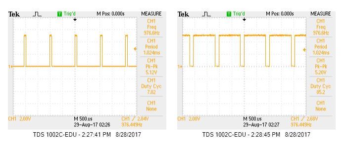
Servos
Now that we understood how to use the pulse width modulation feature, we could program servos to help our robot move throughout the world. Again, this requires some modification to our code. In particular, we have to include a new library which helps us to interface with the servos.

                            #include <Servo.h>

                            Servo myservo;

                            void setup() {
                                myservo.attach(3);
                            }

                            void loop() {
                                myservo.write(180);
                            }
                        

This would cause the servo to run at full speed forward. Because we use continuous motion servos, the parameter passed to the myservo.write() function is the speed of the servo. A value of 0 corresponds to full speed in reverse, 90 is stationary, and 180 is full speed forward.

We then used a screwdriver to manually alter the potentiometer values in order to control the speed and direction of the servo. This required a similar setup as the one used for the variable brightness LED.

Since we had time left in lab, we began to gather materials to start the building of our robot. First, we assembled the base structure which included a chassis to hold the arduino, and two servos connected to wheels.

Using our new knowledge of programming servos, we hooked up a 5V battery back to the arduino and programmed our robot to move forwards, backwards or in a circle.